

A kind of steel belt pretensioning method
A steel belt and grooved technology, applied in the field of robots, can solve the problems of large volume, unsuitable multi-layer steel belt pretensioning, and uncompact structure of the robot steel belt pretensioning device, and achieves small size, compact structure, and occupied volume. small effect
- Summary
- Abstract
- Description
- Claims
- Application Information
AI Technical Summary
Problems solved by technology
Method used
Image

Examples
specific Embodiment approach 1
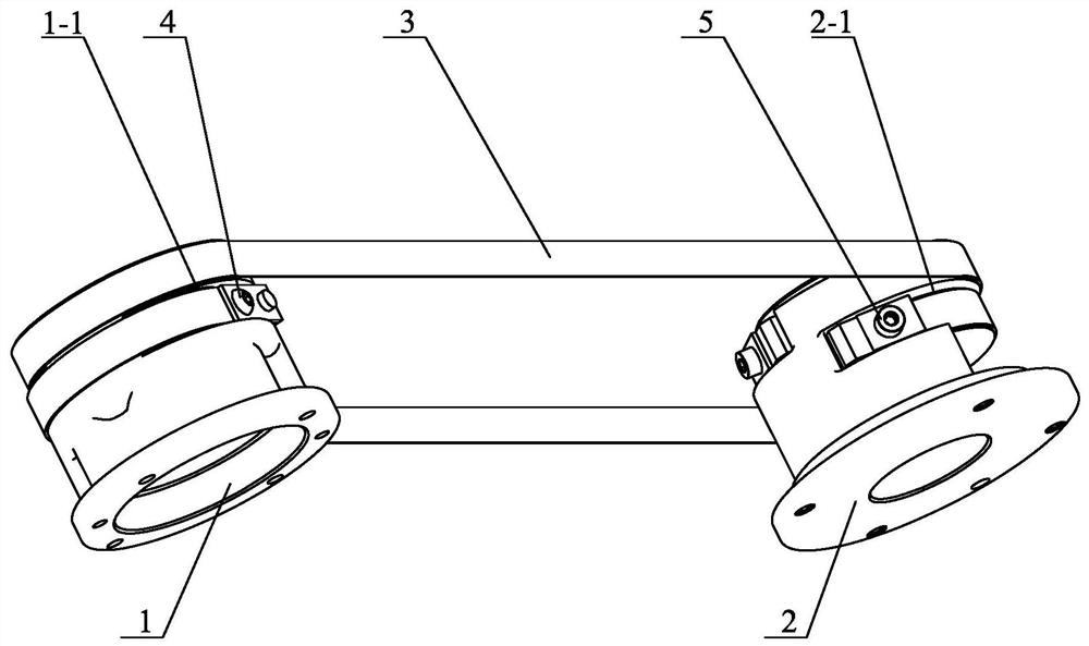
[0022] Specific implementation mode one: combine Figure 1 to Figure 5 To illustrate this embodiment, a steel belt pretensioning device described in this embodiment includes a steel belt pulley A1, a steel belt pulley B2, a steel belt assembly 3, a first fastening screw 4 and a second fastening screw 5, and the steel belt assembly One end of 3 is fixed on the outer peripheral side wall of the steel belt pulley A1 through the first fastening screw 4, and the other end of the steel belt assembly 3 is fixed on the outer peripheral side wall of the steel belt pulley B2 through the second fastening screw 5 superior;
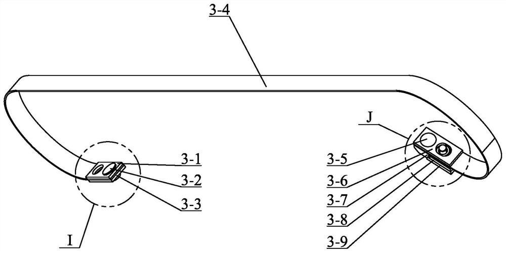
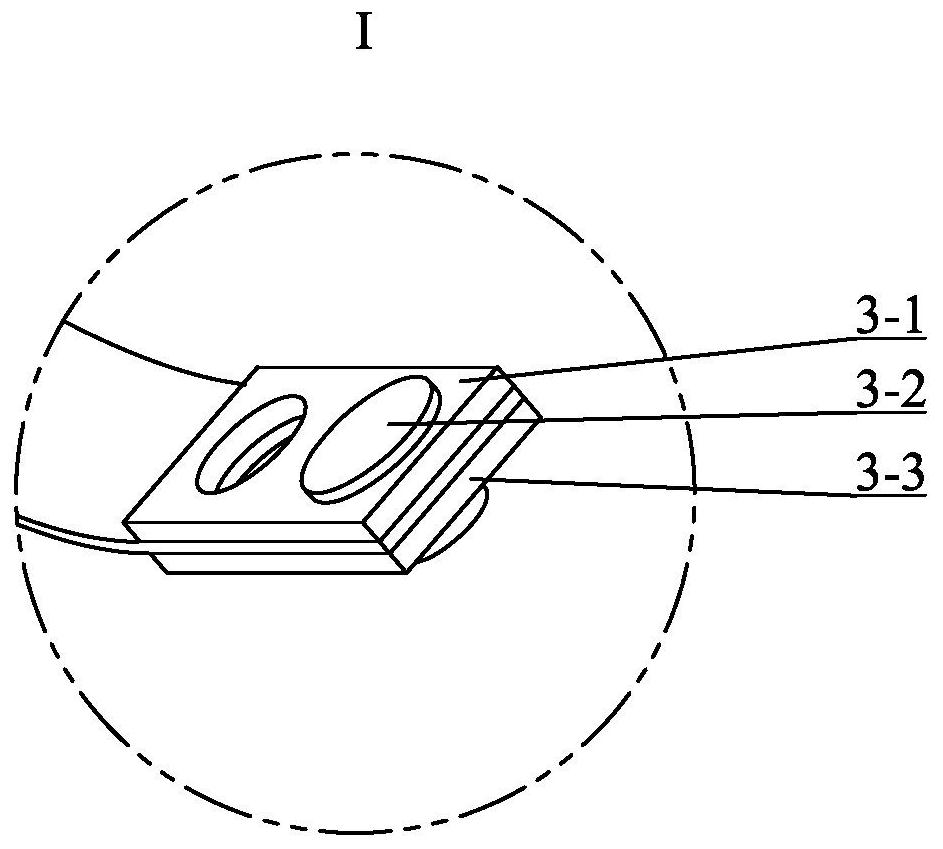
[0023] The steel belt assembly 3 includes a first pressing plate 3-1, a first cylindrical pin 3-2, a second pressing plate 3-3, a second cylindrical pin 3-5, a third pressing plate 3-6, a wedge-shaped pressing plate 3-7 and a fourth Pressing plate 3-9, one end of the steel strip 3-4 is fixedly connected between the first pressing plate 3-1 and the second pressing pla...
specific Embodiment approach 2
[0024] Specific implementation mode two: combination Figure 1 to Figure 5 To illustrate this embodiment, the outer end surface of the fourth pressure plate 3-9 in this embodiment that cooperates with the groove wall of the wedge-shaped groove 3-7-1 is an inclined plane, and the inclined direction of the inclined surface is the same as the inclined direction of the groove wall of the wedge-shaped groove 3-7-1. unanimous. The undisclosed technical features in this embodiment are the same as those in the first embodiment.
[0025] Such a design makes the inclined surface of the fourth pressing plate 3-9 cooperate with the groove wall of the wedge-shaped groove 3-7-1, so as to prevent stress concentration on the fourth pressing plate 3-9.
specific Embodiment approach 3
[0026] Specific implementation mode three: combination figure 1 To illustrate this embodiment, the outer peripheral side wall of the steel belt pulley A1 described in this embodiment is provided with a belt groove A1-1 along the circumferential direction, and one end of the steel belt assembly 3 is clamped in the belt groove A1-1, and the steel belt pulley The outer peripheral side wall of B2 is provided with a belt groove B2-1 along the circumferential direction, and the other end of the steel belt assembly 3 is clamped in the belt groove B2-1. The undisclosed technical features in this embodiment are the same as those in the first or second specific embodiment.
[0027] It is designed in this way to facilitate the axial positioning between the steel belt assembly 3 and the steel pulley A1 and the steel pulley B2.
PUM
 Abstract
Description
Claims
Application Information