Eureka AIR delivers breakthrough ideas for toughest innovation challenges, trusted by R&D personnel around the world.

Welding pressing tool

A technology of tooling and pressing plate, applied in welding equipment, auxiliary welding equipment, welding/cutting auxiliary equipment, etc., can solve problems such as poor pressing effect, crushing or scratching, and unqualified products, so as to improve work efficiency and reduce The effect of displacement bias

Pending Publication Date: 2021-12-31
陈毅
View PDF1 Cites 0 Cited by
  • Summary
  • Abstract
  • Description
  • Claims
  • Application Information

AI Technical Summary

Problems solved by technology

[0004] However, this welding fixture does not consider the following issues when it is used:
[0005] In this technical solution, the slide block on the slide rod is used to press the workpiece to be welded and fixed, but in the actual use process, the lower end surface of the slide block is provided with zigzag stripes, which is easy to cause the welding workpiece itself and the workpiece to be welded in the process of pressing the welding workpiece. The surface is crushed or scratched, resulting in unqualified products, and the fixing effect of this method is not good enough; especially for irregular welding workpieces, the pressing effect is poor; it is inconvenient to adjust the angle of the welding workpiece

Method used


Image

  • Welding pressing tool
  • Welding pressing tool
  • Welding pressing tool

Examples


Embodiment Construction

[0027] The following will clearly and completely describe the technical solutions in the embodiments of the present invention with reference to the accompanying drawings in the embodiments of the present invention. Obviously, the described embodiments are only some, not all, embodiments of the present invention. Based on the embodiments of the present invention, all other embodiments obtained by persons of ordinary skill in the art without making creative efforts belong to the protection scope of the present invention.

[0028] see Figure 1 to Figure 7 , the present invention provides a technical solution:

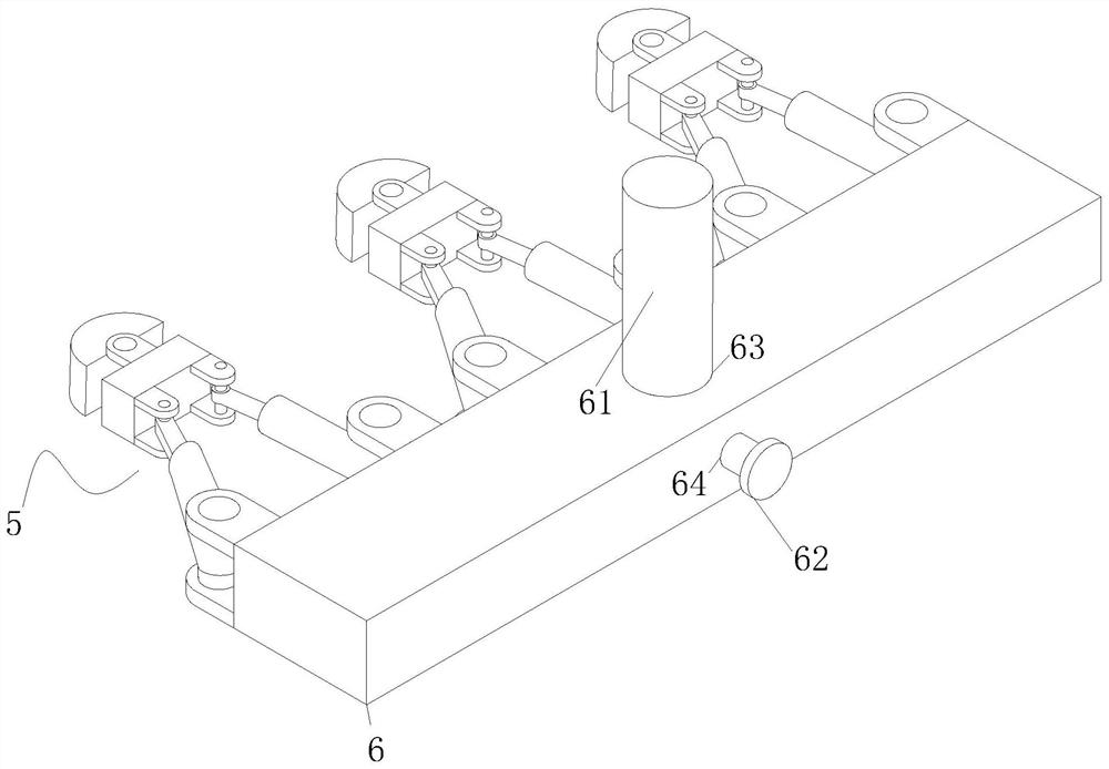
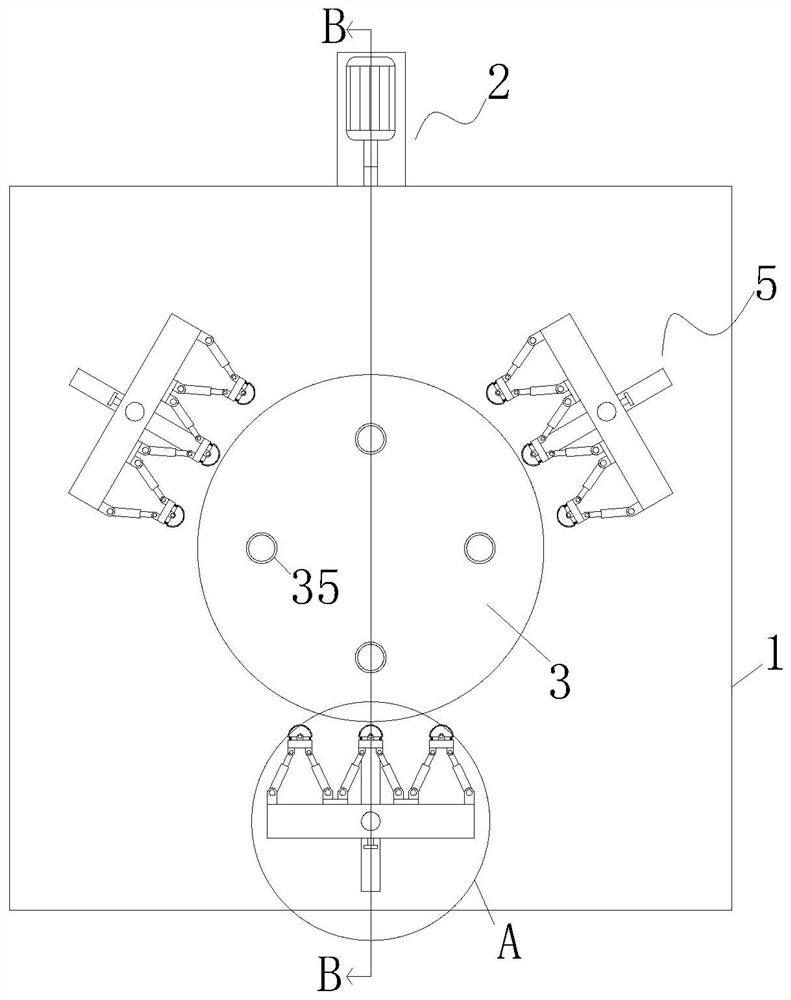
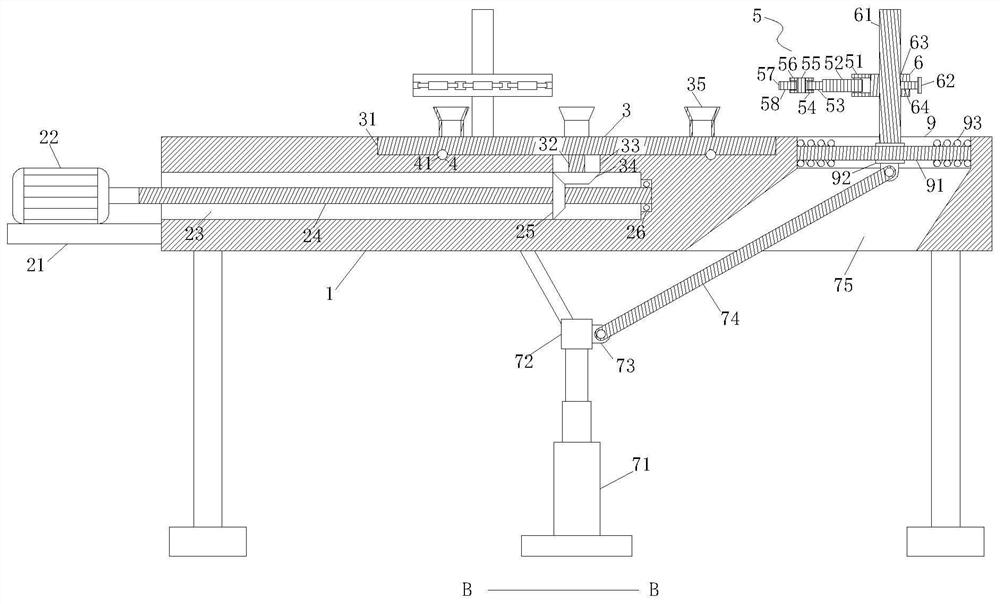
[0029]A welding and pressing tooling, comprising a processing table 1, a placing plate 3 is arranged at the center of the upper end surface of the processing table 1, and three movable plates 6 are arranged at an equal distance on the outer side of the placing plate 3, and the three movable plates 6 The inner surface is equidistantly provided with three pressing mechanis...


PUM


Abstract

The invention relates to the technical field of welding, in particular to a welding pressing tool which comprises a machining table. A placing plate is arranged in the center of the upper end face of the machining table, three movable plates are annularly arranged on the outer side of the placing plate at equal intervals, and three pressing mechanisms are arranged on the inner side faces of the three movable plates at equal intervals. Each pressing mechanism comprises first-stage hinge seats, sleeves, spring grooves, first-stage springs, movable rods, second-stage hinge seats, a supporting block, a third-stage hinge seat, a rubber pad, a clamping plate and second-stage springs. Rectangular grooves are symmetrically formed in the left side and the right side of the center position of the inner side face of each movable plate, and sliding blocks are arranged in the rectangular grooves correspondingly. The second-stage hinge seats are fixedly connected to the left sides and the right sides of the front side faces of the supporting blocks correspondingly, and the front ends of the movable rods are hinged to the second-stage hinge seats correspondingly. According to the welding pressing tool, the pressing mechanisms are pulled by a pressing driving mechanism to contract inwards, so that a welding workpiece is pressed, manual operation is avoided, time and manpower are saved, and the working efficiency is improved.

Description

technical field [0001] The invention relates to the field of welding technology, in particular to a welding pressing tool. Background technique [0002] Welding tooling is a set of flexible welding fixing, pressing and positioning fixtures, mainly used for welding various weldable materials, large, medium and small materials. During the trial welding process, it is necessary to position and compress the tooling assembly of the workpiece to be welded to prevent the deviation of welding accuracy due to insufficient tooling pressing force due to external factors. [0003] Existing patent (notification number: CN207494877U) a welding fixture, including a clamping table, the clamping table is provided with a through hole and a positioning pin, the positioning pin is arranged on one side of the through hole, and the through hole is located In the middle part of the clamping table, the through hole is used to place the part to be welded, and a fixing device is respectively arrange...

Claims


Application Information

Patent Timeline
Patent Type & Authority Applications(China)
IPC IPC(8): B23K37/047B23K37/04
CPCB23K37/047B23K37/0443
Inventor 陈毅田逸飞王帅
Owner 陈毅
Why Eureka
Eureka Blog
Learn More