Automatic feeding and storing device

An automatic material feeding and material storage technology, applied in the field of material storage, can solve the problems of increased collision strength, material wear, noise, etc., to reduce the rolling speed of materials, prevent material deformation and damage, and facilitate the storage state.

Pending Publication Date: 2021-12-31
江阴金属材料创新研究院有限公司
View PDF9 Cites 2 Cited by
  • Summary
  • Abstract
  • Description
  • Claims
  • Application Information

AI Technical Summary

Problems solved by technology

[0003] However, in the above-mentioned feeding device, the inclination angle of the partition is fixed. When in use, the material rolls down along the inclined partition, and the speed will gradually increase, resulting in an increase in the collision strength between the partition and the inner wall of the storage box when it passes through the discharge port. , lead to material wear and even deformation, and noise will be generated due to violent collision during the material storage process; not only that, in the above-mentioned feeding device, it is difficult for the staff to obtain the total amount of material stored in the storage box, resulting in frequent occurrence There are too many materials stored in the storage box and it is impossible to continue to store materials or the storage box is empty, so it is difficult to provide materials for production use; During the process, it is difficult to ensure that the materials are accurately placed in the designated location, which affects the normal storage of materials

Method used


Image

  • Automatic feeding and storing device
  • Automatic feeding and storing device
  • Automatic feeding and storing device

Examples


Embodiment Construction

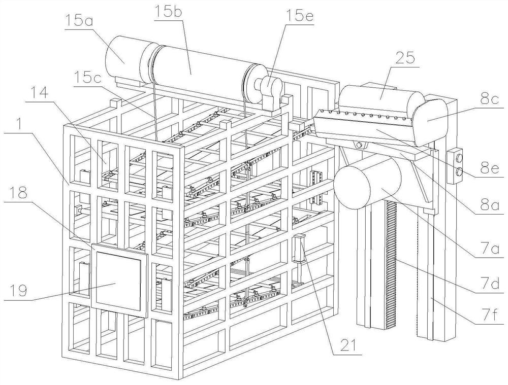
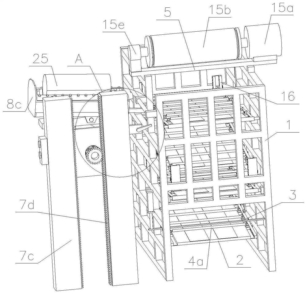
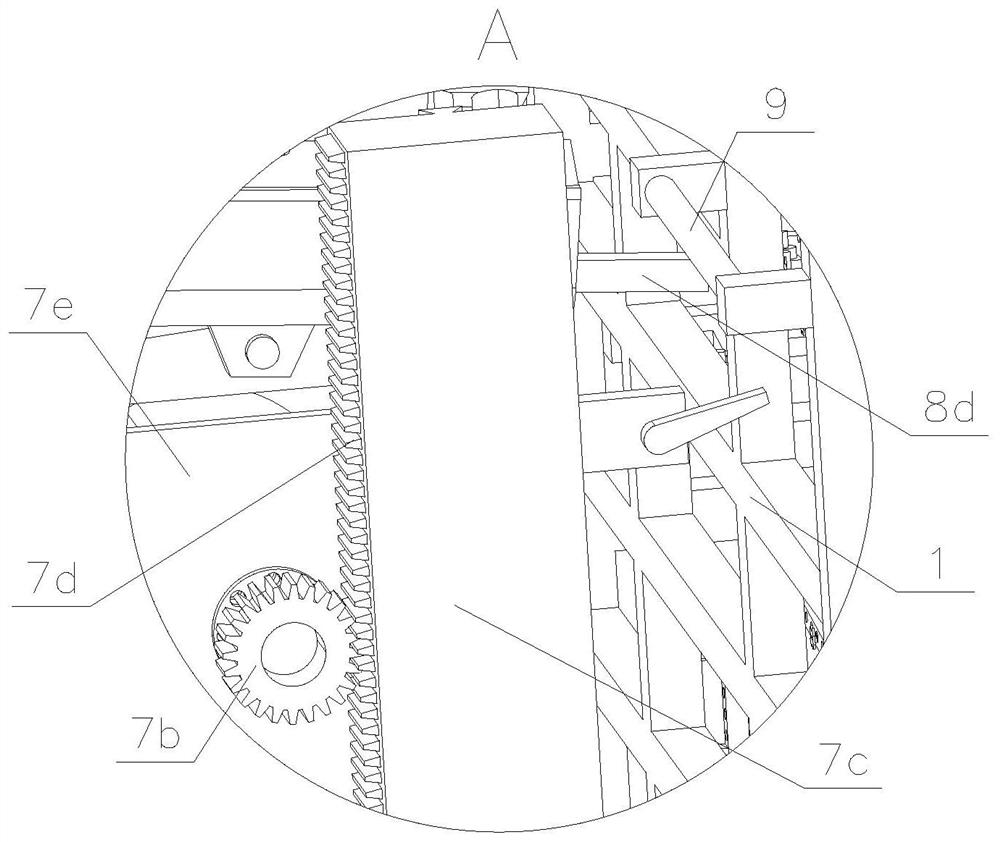
[0030] DETAILED DESCRIPTION OF THE PREFERRED EMBODIMENTS The following examples are for more clearly explaining the technical solutions of the present invention without limiting the scope of the invention.

[0031] like Figure 1 - Figure 12 , The automatic feeding material storage apparatus of the invention, the main material for the single fixed cylindrical specification model 25, comprising a storage rack, a storage rack comprising four vertically disposed and sequentially connected end to end bracket, four brackets are formed stocker enclosed space, wherein the bottom of the storage rack 1 is provided with a discharge opening at one end, wherein the top side is provided with a feed inlet; provided four longitudinal direction with an inclined direction in which material storage space height down plate stocker 2, the stocker 2 is a rectangular plate, two inclined directions stocker plate 2 adjacent the contrary, the stocker plate 2 four enclosed channels formed tortuous stocker, ...


PUM


Abstract

The invention discloses an automatic feeding and storing device which comprises a storing frame. A plurality of obliquely downward storing plates are distributed on the storing frame in the height direction of the storing frame; the adjacent storing plates enclose to form a zigzag storing passage; an intercepting part is movably arranged at the output end of the storing passage; speed reducing parts are arranged in the storing passage at intervals in the storing direction of the storing passage; the speed reducing parts are connected with a pressure sensor; the speed reducing parts comprise straight-through speed reducing parts arranged on the storing plate and corner speed reducing parts arranged on the storing frame; the interval between every two adjacent straight-through speed reduction parts is equal to the diameter of a material; and a feeding mechanism is arranged in a mode of directly facing the input end of the storing passage. According to the automatic feeding and storing device, the speed reducing parts are used for buffering and reducing the rolling speed of the material, so that collision is relieved, noise is reduced, the material is prevented from being deformed and damaged, the interval and the positions of the speed reducing parts are limited, the material is guaranteed to be abutted against the speed reducing parts during storage, then a pressure sensor detects pressure signals, and a current material storage amount of the device is determined according to the signal quantity.

Description

Technical field [0001] The present invention relates to material storage technology, and particularly relates to an automatic feeding material storage means. Background technique [0002] In the prior art, in order to facilitate storage or cylindrical pipe material (such as metal pipes, rollers), generally provided on the frame a plurality of inclined plate stocker, each material was between reservoir plate "" shape distributed. The Gazette No. CN208034046U Chinese invention discloses a robotic automatic feeding device, comprising a substrate, a feeding robot and transshipment vehicles, transport vehicles comprising a base material, and moving wheels storage bin, the bottom plate horizontally disposed, storage bin the height direction thereof is provided with a plurality of inclined spacer blocks, the side with the inner wall of the storage tank is fixed to the separator, the separator and the side of each block are left blanking rectangular aperture adjacent two partition plates...

Claims


Application Information

Patent Timeline
Patent Type & Authority Applications(China)
IPC IPC(8): B65G1/14
CPCB65G1/14
Inventor 王旭
Owner 江阴金属材料创新研究院有限公司
Why Eureka
Try Eureka