[0036] The technical solutions of the present invention will be clearly and completely described below with reference to the embodiments. Obviously, the described embodiments are part of the embodiments of the present invention, but not all of the embodiments. Based on the embodiments of the present invention, all other embodiments obtained by those of ordinary skill in the art without creative efforts shall fall within the protection scope of the present invention.
[0037] In the description of the present invention, it should be understood that the terms "center", "longitudinal", "lateral", "length", "width", "thickness", "upper", "lower", "front", " Or The positional relationship is based on the orientation or positional relationship shown in the accompanying drawings, which is only for the convenience of describing the present invention and simplifying the description, rather than indicating or implying that the referred device or element must have a specific orientation, be constructed and operated in a specific orientation, Therefore, it should not be construed as a limitation of the present invention.
[0038]In addition, the terms "first" and "second" are only used for descriptive purposes, and should not be understood as indicating or implying relative importance or implying the number of indicated technical features. Thus, features defined as "first", "second" may expressly or implicitly include one or more of said features. In the description of the present invention, "plurality" means two or more, unless otherwise expressly and specifically defined. In addition, the terms "installed", "connected" and "connected" should be understood in a broad sense, for example, it may be a fixed connection, a detachable connection, or an integral connection; it may be a mechanical connection or an electrical connection; it may be It is directly connected, or it can be indirectly connected through an intermediate medium, and it can be the internal connection of two components. For those of ordinary skill in the art, the specific meanings of the above terms in the present invention can be understood in specific situations.
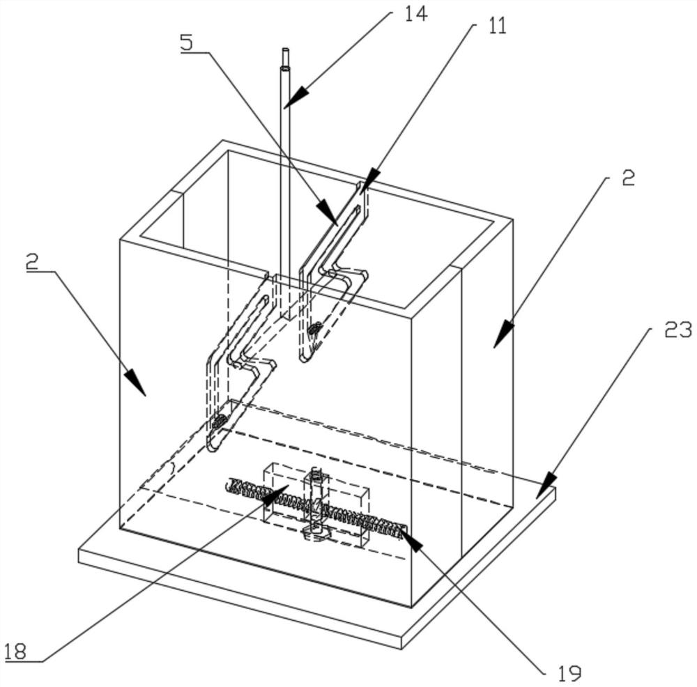
[0039] like Figure 1-Figure 11 shown:
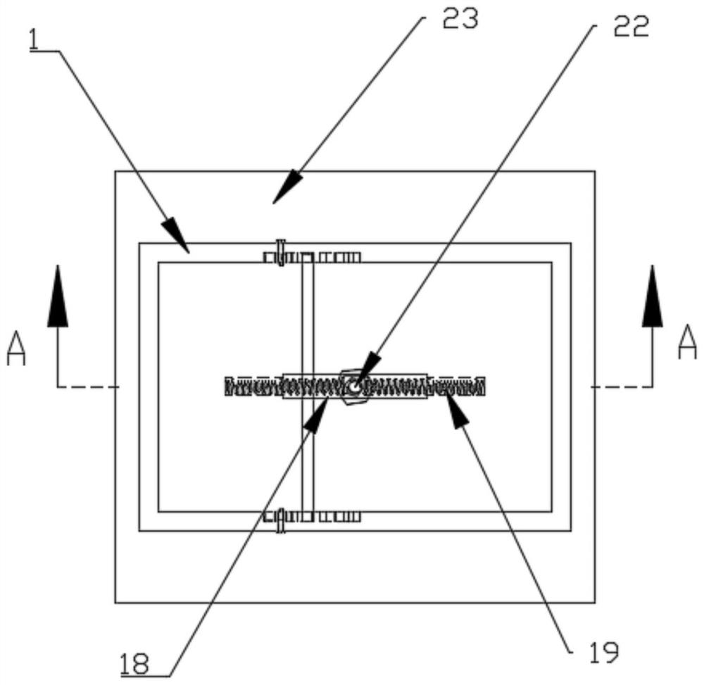
[0040] An automatic clutch with double oblique straight grooves in rectangular section, comprising a clutch box 1, the clutch box 1 includes two identical half boxes 2, the two half boxes 2 are combined to form a clutch box 1, and the two half boxes The bottom wall of 2 is provided with a groove 3 which is recessed inward, and the grooves 3 on the two half boxes 2 are spliced to form a rectangular through groove 4 .
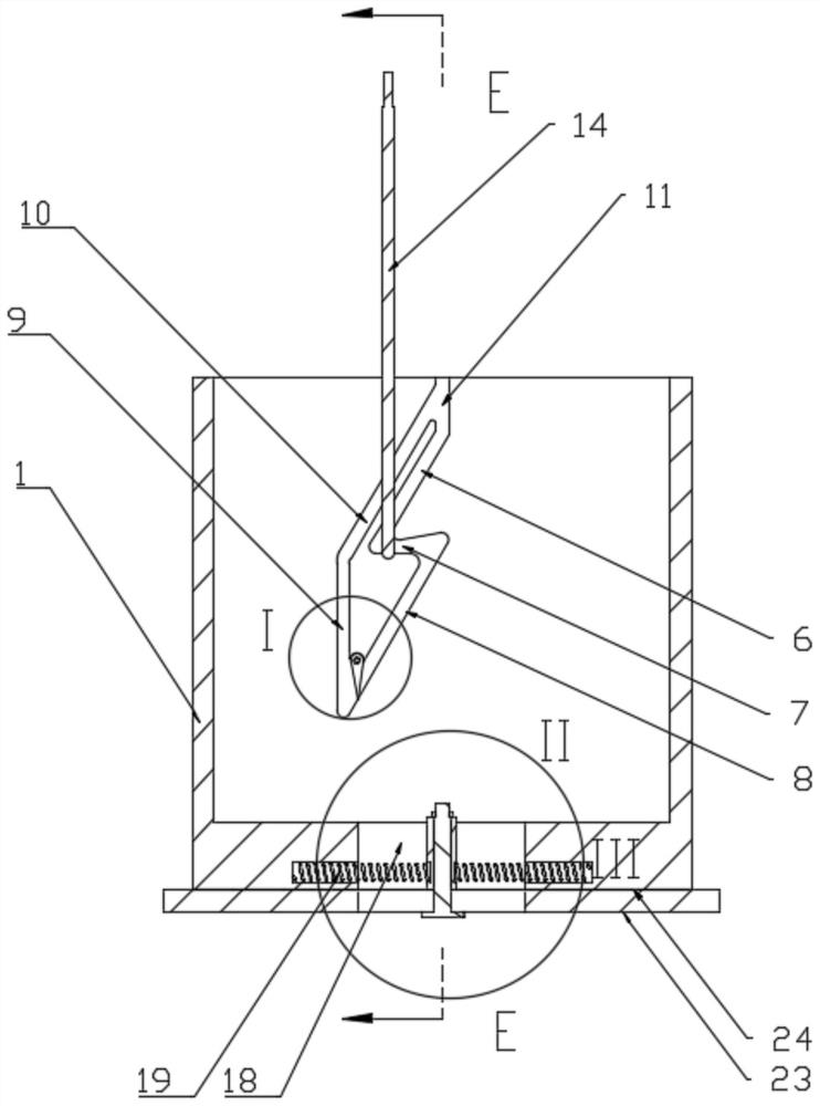
[0041] The two opposite side walls of the clutch box 1 are respectively provided with symmetrically arranged chutes 5. The chutes 5 include a first inclined descending slideway 6, a horizontal slideway 7, a second inclined descending slideway 8, a vertical Straight ascending slideway 9, inclined ascending slideway 10 and vertical opening groove 11, first inclined descending slideway 6, horizontal slideway 7, second inclined descending slideway 8, vertical ascending slideway 9, inclined ascending slideway The chute 10 and the opening slot 11 are connected in sequence and finally closed to form the chute 5 .
[0042] The first inclined downward slide 6 and the second inclined downward slide 8 are arranged in parallel to each other, the bottom end of the first inclined downward slide 6 and the top end of the second inclined downward slide 8 are communicated through the horizontal slide 7, and the inclined upward slide The bottom of 10 is communicated with the bottom of the second inclined descending slideway 8 through the vertical ascending slideway 9 , and the inclined ascending slideway 10 is arranged in parallel with the first inclined descending slideway 6 or the second inclined descending slideway 8 . The top end of the inclined upward slideway 10 and the top end of the first inclined downward slideway 6 are communicated through an open groove 11, and the open groove 11 extends to the top of the clutch box 1;
[0043] The connection between the horizontal slideway 7 and the second inclined downward slideway 8 is provided with a lifting slot 12 with an upwardly concave arc structure. The opening slot 11 and the lifting slot 12 are both located at the middle position of the clutch box 1. The hoisting grooves 12 are located in the same vertical linear direction.
[0044] One end of the second inclined downward slide 8 close to the vertical upward slide 9 is provided with a guide eccentric cam 13 . The side close to the vertical ascending slideway 9 rotates inwardly, and the length of the guiding eccentric cam 13 is greater than the width of the second inclined descending slideway 8; direction of rotation. After the lifting lug rod descends from the contact of the guiding eccentric cam 13, the guiding eccentric cam 13 can maintain the downward drooping state under the action of its own weight, and is just stuck on the inner side of the second inclined downward slide 8, returning the lifting lug rod to the second The channel of the inclined downward slide 8 is blocked to prevent the lifting lug rod from returning to the second inclined downward slide 8 .
[0045] The hoisting rod 14 has a T-shaped structure, and the hoisting rod 14 includes a main hanger rod 15 arranged vertically and a hanger rod 16 vertically arranged and fixedly connected with the main hanger rod 15 , and the two ends of the hanger rod 16 can be in the chute 5 Free sliding; both ends of the ear bar 16 are respectively provided with rollers 17 , and the rollers 17 are rotatably connected with the end of the ear bar 16 .
[0046] A connecting block 18 is connected in the rectangular through groove 4 at the bottom of the clutch box 1. The connecting block 18 and the clutch box 1 can slide relative to each other through the rectangular through groove 4. The opposite sides of the connecting block 18 are connected to the clutch box. A return spring 19 is symmetrically arranged between the inner walls. There are positioning holes 20 on the side walls where the connecting block 18 is connected with the return spring 19. One end of the return spring 19 is fixed in the positioning hole 20. The middle of the connecting block 18 is provided with a through hole 21 along the height direction. Connecting bolts 22.
[0047] The above-mentioned method for hoisting an automatic clutch with a double oblique straight groove with a rectangular section includes the following steps:
[0048] Step 1. Connect and lift
[0049] The lower part of the clutch box 1 is connected to the hoisted member 23 through the connecting block 18, the hoisting rod 14 extends downward from the opening slot 11 into the first inclined downward slideway 6, and the hoisting lug rod 16 is in a horizontal state on both sides corresponding to each other. The two first inclined downward slides 6 on the wall move vertically downward, and force the clutch box 1 to move horizontally, the return spring 19 is elastically deformed, the lifting lug rod 16 reaches the bottom of the first inclined downward slide 6, and the lifting The ear bar stops moving, the return spring 19 pushes the clutch box 1 back to the initial position, the ear bar 16 reaches the lifting groove 12 at the top of the second inclined downward slide 8 along the horizontal slideway 7, and the lift bar 14 moves upward at this time. , the hoisting rod 14 drives the clutch box 1 to move upward through the hoisting groove 12, thereby driving the hoisted piece 23 to rise to complete the hoisting;
[0050] Step 2. Separation of the lifting rod
[0051] When it is lifted to the final position by the lifting member 23 and needs to be separated, the lifting rod 14 moves vertically downward along the second inclined downward slideway 8, and forces the clutch box 1 to move horizontally, the return spring 19 is elastically deformed, and the lifting lug rod 16 reaches the first position. After the bottom end of the two inclined downward slides 8, the lifting lug rod changes from downward to vertical upward. Due to the action of the guiding eccentric cam, the lifting rod 14 vertically rises along the vertical upward slide 9, and reaches the inclined upward slide 10. The lug bar 16 vertically rises along the inclined upward slideway 10 to the open slot 11. During this process, the return spring 19 pushes the clutch box 1 back to the initial position, the lug bar 16 continues to rise, and finally escapes from the open slot 11, The separation of the lifting rod 14 and the clutch box 1 is realized, and the separation of the lifting rod 14 and the lifted member 23 is realized.
[0052] When the present invention works,
[0053] The lug rods 16 with rollers 18 at both ends enter vertically downward from the ports o of the open grooves 11 on both sides of the clutch box 1 , and descend in the direction of the open grooves 11 (the oa direction) and enter the first inclined downward slideway 6 The lifting rod 14 drives the lifting lug rod 16 to continue to move vertically downward, and forces the clutch box to move to the right, (at this time, it is consolidated into one by the lifting member 23, the anti-friction pad 24, the connecting block 18 and the connecting bolt 22 And form a sliding connection with the clutch box 1) Because the return spring 19 is installed between the fixed connection block 18 and the horizontally movable clutch box 1), the return spring 19 is deformed by force; it can be understood as a lifting lug The relative movement of 16 in the direction of ab in the figure, when the lifting lug rod 16 reaches the bottom end of the first inclined downward slideway 6, the return spring 19 pushes the clutch box 1 to return to the original equilibrium position, and the lifting lug rod 16 moves along the figure. Moving in the bc direction, the lifting lug bar 16 is located in the lifting groove 12 at the top of the second inclined downward slideway 8. Since the lifting groove 12 is recessed upward, the lifting rod 14 drives the lifting lug rod 16 through the cooperation of the lifting groove 12, and can The clutch box 1 and the hoisted member 23 are driven to rise to realize hoisting.
[0054] When the lifting is completed and it needs to be separated, the lifting rod 14 continues to descend vertically along the second inclined downward slide 8, the clutch box 1 is squeezed by the lifting lug rod 16 and slides to the right, and the return spring 19 is deformed by force, which can be understood as a lifting The relative movement of the ear bar 16 along the cd direction in the figure, when the ear bar 16 goes over the guide eccentric cam 13 (point d in the figure) and continues to descend, the guide eccentric cam 13 reverses and blocks the movement of the ear bar 16 from point e to c. Path, when the lifting lug rod 16 (roller 17) continues to descend straight point e, the lifting rod 14 stops descending and rises vertically along the vertical ascending slideway 9 (in the direction of ef in the figure), and after reaching the inclined ascending slideway 10, the return spring Under the action of 19, the clutch box 1 is reset to the original equilibrium position. During this process, the lifting lug rod 16 vertically rises to the opening groove 11 along the inclined upward slide 10 (equivalent to the lifting lug rod 16 moving in the direction of fg), and the lifting lug The rod 16 continues to rise and finally escapes from the opening 0 of the opening slot 11 , realizing the separation of the hoisting rod 14 from the clutch box 1 , and realizing the separation of the hoisting rod 14 and the hoisted member 23 .
[0055] During the above working process of the present invention, both ends of the lug bar 16 and the rollers 17 are always in the chute 5, the hoist bar 14 only moves vertically, and the lug bar 16 of the hoist bar 14 is moved from the initial position to the opening slot 11 and the The first inclined downward slideway 6 moves vertically downward, and when the lifting lug rod 16 moves to the bottom end of the first inclined downward slideway 6 , the movement is stopped. The clutch box 1 returns to the initial equilibrium position under the action of the return spring 19, and at the same time, the lifting lug rod 16 reaches the lifting groove 12, and the lifting rod 14 moves upward to realize the lifting of the lifted piece;
[0056] When lifting to the predetermined position, the lifting rod 14 needs to be separated from the clutch box 1, the lifting lug rod 16 of the lifting rod 14 moves vertically downward along the second inclined downward slide 8 on the inner wall of the clutch box 1, and when the lifting rod 16 crosses the After guiding the eccentric cam 13, the lifting lug rod 16 vertically rises along the vertical ascending slideway 9, and after reaching the inclined ascending slideway 10, under the action of the return spring 19, the clutch box 1 is reset to the original equilibrium position. The ear bar 16 vertically rises to the opening slot 11 along the inclined upward slide 10, the lifting ear bar 16 continues to rise, and finally comes out from the opening of the opening slot 11, realizing the separation of the lifting bar 14 and the clutch box 1, and realizing the lifting bar 14 Separation from the lifted member 23 .
[0057] The present invention realizes that the hoisting rod 14 only moves vertically, and uses the linear movement of the hoisting rod 14 as the power and motion control parameters, and uses the first inclined downward slide 6 , the horizontal slide 7 and the second inclined downward slide 8 , the vertical ascending slideway 9, the inclined ascending slideway 10 and the opening groove 11, as well as the coordinated movement of the connecting block 18 and the return spring 19, automatically realize the autonomous clutch of the hoisting rod 14 and the hoisted piece 23, avoiding the complexity of the traditional clutch The auxiliary completion of the hydraulic and electromagnetic control systems, etc., simplifies the mechanism, reduces the control cost, and improves the reliability of the system.
[0058] Finally, it should be noted that the above embodiments are only used to illustrate the technical solutions of the present invention, but not to limit them; although the present invention has been described in detail with reference to the foregoing embodiments, those of ordinary skill in the art should understand that: The technical solutions described in the foregoing embodiments can still be modified, or some or all of the technical features thereof can be equivalently replaced; and these modifications or replacements do not make the essence of the corresponding technical solutions deviate from the technical solutions of the embodiments of the present invention. scope.