Rotary anchor construction manipulator and trolley

A bolt construction, wheel-type technology, applied to the installation of bolts, instruments, mining equipment, etc., can solve the problems of cycle time consumption, small prestress, and many quality control nodes, so as to improve construction efficiency and effectiveness , Reduce the effect of applying space

Active Publication Date: 2022-04-01
CHINA UNIV OF MINING & TECH (BEIJING) +1
View PDF0 Cites 0 Cited by
  • Summary
  • Abstract
  • Description
  • Claims
  • Application Information

AI Technical Summary

Problems solved by technology

[0003] The bolt construction equipment in the prior art has a single function, and the drilling process is separated from the bolt installation process. It can only be constructed specifically for one kind of bolt, and it is impossible to dynamically select the most suitable anchor according to the actual drilling surrounding rock conditions. For rod support, individual construction steps require manual intervention, such as using high-strength clip-type locks for locking, and the tensioning process requires manual high-altitude tensioning operations. This process has a greater construction risk and consumes a lot of energy. construction cycle time
The construction equipment of the existing technology can no longer meet the construction requirements of the current high-strength prestressed anchor, especially in the past when the prestress was applied based on torque, the prestress applied by this structure is generally small, and the effect of the high-strength prestressed anchor cannot be fully to play
The construction equipment in the prior art has no effective detection of bolt construction quality such as grouting quality and prestress value, but bolt support, as a hidden project, has the characteristics of many quality control nodes and lacks reliable monitoring and detection means The characteristics of closed-loop feedback make it difficult to guarantee the quality of tension construction

Method used


Image

  • Rotary anchor construction manipulator and trolley
  • Rotary anchor construction manipulator and trolley
  • Rotary anchor construction manipulator and trolley

Examples


Embodiment Construction

[0028] Example embodiments will now be described more fully with reference to the accompanying drawings. Example embodiments may, however, be embodied in many forms and should not be construed as limited to the embodiments set forth herein; rather, these embodiments are provided so that this disclosure will be thorough and complete, and will fully convey the concept of example embodiments to those skilled in the art. The same reference numerals in the drawings denote the same or similar structures, and thus their detailed descriptions will be omitted.

[0029] The terms "a", "an", "the", "said" are used to indicate the presence of one or more elements / components / etc; the terms "comprising" and "have" are used to indicate an open-ended inclusion means and means that additional elements / components / etc. may be present in addition to the listed elements / components / etc.

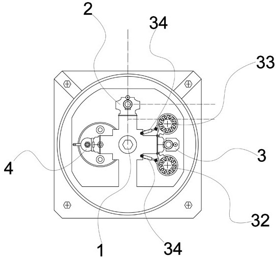
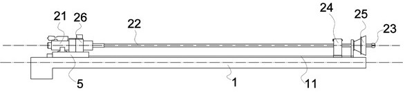
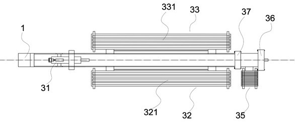
[0030] Such as Figure 1 to Figure 5 as shown, figure 1 It shows a front view of a wheel-type bolt construc...


PUM


Abstract

The invention provides a runner-type anchor construction manipulator and a trolley. The runner-type bolt construction manipulator includes a central shaft, a drilling assembly, a bolt installation assembly and a post-processing assembly arranged around the central shaft. The drilling assembly is provided with a data acquisition instrument that is electrically connected to a control system. In order to monitor whether there is a sudden change in the surrounding rock structure during the drilling process; the bolt installation assembly includes a bolt installation machine, and a prestressed bolt warehouse and a grouting bolt warehouse respectively arranged on both sides of the bolt installation machine; The post-processing component is connected to the third guide rail to perform post-processing on the prestressed bolt body or the grouting bolt body driven into the surrounding rock. The patent obtains the integrity and fragmentation degree of the surrounding rock by analyzing the drilling data, so as to adaptively select the type of prestressed bolt or grouting bolt for construction, effectively ensure the construction quality of the bolt, ensure the safety of workers, and improve the Work efficiency, realize automatic, mechanized and digital bolt construction.

Description

technical field [0001] The invention relates to the technical field of tunnel construction, in particular to a wheel-type bolt construction manipulator and trolley. Background technique [0002] With the continuous development of geotechnical engineering and the continuous pursuit of new Austrian methods by many experts and scholars, the support form that uses the anchor rod as the support structure to mobilize the self-bearing capacity of the surrounding rock can effectively control the settlement of the surrounding rock and thus restrict the tunnel opening. In the process of excavation, the damage that may extend to the surface, bolt support is one of the mainstream support methods in underground concealed projects such as former tunnels and chambers. However, the rock formation is a complex heterogeneous structure, due to the differences in lithology, structure, weathering degree, compressive strength, rock structure and mineral composition of the surrounding rocks. The ...

Claims


Application Information

Patent Timeline
Patent Type & Authority Patents(China)
IPC IPC(8): E21D20/00E21D20/02E21B44/00G01D21/02
CPCE21D20/003E21D20/02E21D20/028E21D20/006E21D20/00E21B44/00G01D21/02
Inventor 史志远边文辉詹家旺李珅张连军徐东明刘永亮
Owner CHINA UNIV OF MINING & TECH (BEIJING)
Why Eureka
Try Eureka