Axial flow compressor for improving full-cycle flow field

A technology of axial flow compressor and flow field, which is applied to components, mechanical equipment, machines/engines, etc. of pumping devices for elastic fluids, and can solve the problems of compressor performance optimization that cannot be guaranteed at all times, distortion area changes, local Static vane modification is no longer applicable and other problems, to achieve the effect of eliminating the flow separation range, improving the flow capacity, and improving the flow field structure around the circumference

Pending Publication Date: 2021-12-31
CIVIL AVIATION UNIV OF CHINA
View PDF0 Cites 1 Cited by
  • Summary
  • Abstract
  • Description
  • Claims
  • Application Information

AI Technical Summary

Problems solved by technology

[0004] However, the location of local distortion needs to be predicted according to the actual situation. In practical applications, the distortion area may change; and, when it is in the middle stage of the compressor and later, after the diversion of the previous stages, the airflow distribution in the circumferential direction has become relatively Uniform, partial vane modification schemes are no longer applicable
Therefore, there are limitations in the application of the above-mentioned non-axisymmetric distributed vane axial-flow compressor, and it is impossible to guarantee the optimization of compressor performance at all times.

Method used


Image

  • Axial flow compressor for improving full-cycle flow field
  • Axial flow compressor for improving full-cycle flow field
  • Axial flow compressor for improving full-cycle flow field

Examples


Embodiment Construction

[0029] It should be noted that, in the case of no conflict, the embodiments of the present invention and the features in the embodiments can be combined with each other.

[0030] In describing the present invention, it should be understood that the terms "center", "longitudinal", "transverse", "upper", "lower", "front", "rear", "left", "right", The orientations or positional relationships indicated by "vertical", "horizontal", "top", "bottom", "inner", "outer", etc. are based on the orientation or positional relationships shown in the drawings, and are only for the convenience of describing the present invention Creation and simplification of description, rather than indicating or implying that the device or element referred to must have a specific orientation, be constructed and operate in a specific orientation, and therefore should not be construed as limiting the invention. In addition, the terms "first", "second", etc. are used for descriptive purposes only, and should no...


PUM


Abstract

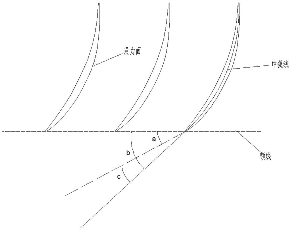
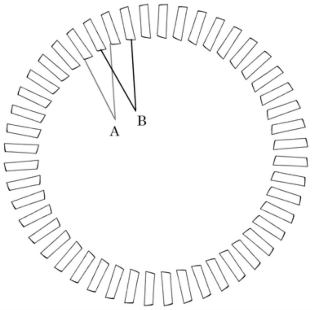
The invention provides an axial flow compressor for improving a full-cycle flow field. In full-cycle stationary blades of a stator, large attack angle blades and small attack angle blades are alternately arranged, and the flow channel gaps among the blades are the same. In the full-cycle stationary blades of the stator, prototype blades and modified blades are alternately arranged, the gaps between the prototype blades and the two adjacent modified blades are the same, and the attack angle of the modified blades is smaller than that of the prototype blades. According to the axial flow compressor, the prototype blades in a prototype stator are partially or completely replaced by the modified blades capable of inhibiting the angular region separation of the suction surface, so that the structure of the full-cycle flow field is improved, and the through-flow capability is improved. According to the structure, stable operation under the working condition that an original stator blade profile can operate can be guaranteed, meanwhile, the flow field structure under the near-stall working condition can be greatly improved, and the flow separation range of an angular region of the suction surface is reduced or even eliminated.

Description

technical field [0001] The invention belongs to the technical field of aero-engine design and research, and in particular relates to an axial-flow compressor for improving the flow field around the entire circumference. Background technique [0002] Compressor is one of the three core components of contemporary aero-engines, among which axial-flow compressors are widely used in large aero-engines. In order to meet the high performance requirements of contemporary aero-engines, it is necessary to improve the compressor's anti-load capacity, efficiency and stability margin. The stator of a conventional axial flow compressor is arranged by the blades of the same blade shape with a certain consistency. When the incoming flow is uniform, the angle of attack of the incoming flow of each stator blade is approximate. The state is close. When the compressor is in a high-load operation state, due to the large reverse pressure gradient, the flow separation in the corner area of ​​the...

Claims


Application Information

Patent Timeline
Patent Type & Authority Applications(China)
IPC IPC(8): F04D29/54F04D29/66
CPCF04D29/542F04D29/667
Inventor 傅文广孙鹏王威王伟陶立权
Owner CIVIL AVIATION UNIV OF CHINA
Why Eureka
Try Eureka