
Solid rocket cold separation device and using method thereof

A solid rocket, cold separation technology, applied in the field of rocket separation, can solve the problems of complex timing and large overall quality, and achieve the effect of simple timing

Pending Publication Date: 2021-12-31
BEIJING ONESPACE TECH CO LTD +4
View PDF5 Cites 0 Cited by
  • Summary
  • Abstract
  • Description
  • Claims
  • Application Information

AI Technical Summary

Problems solved by technology

[0005] Aiming at the deficiencies in the prior art, the present invention provides a solid rocket cold separation device and its use method, which solves the technical problems of large overall mass and complex timing in the prior art

Method used


Image

  • Solid rocket cold separation device and using method thereof
  • Solid rocket cold separation device and using method thereof
  • Solid rocket cold separation device and using method thereof

Examples


Embodiment 1

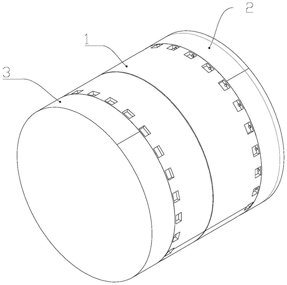
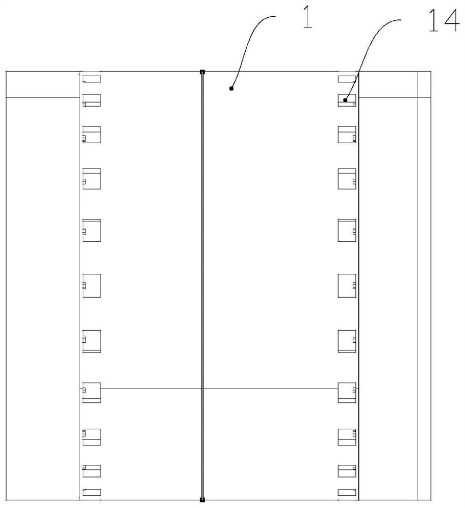
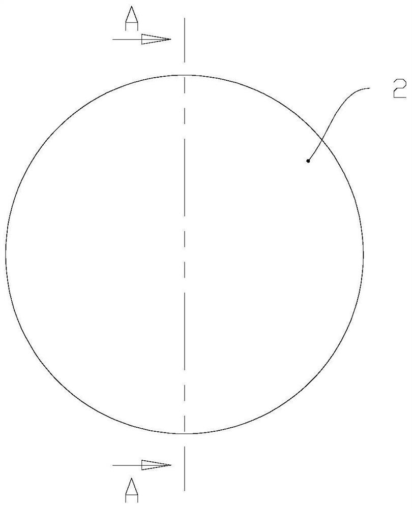
[0043] Such as Figure 1-Figure 11 As shown, a solid rocket cold separation device includes an interstage section 1, and the two ends of the interstage section 1 are respectively connected to the rear skirt 2 of the upper stage engine and the front skirt 3 of the lower stage engine to form a separable interstage The cavity is located on the interstage cavity and is provided with an upper-level engine nozzle 4 and a lower-level engine front head 5; also includes:

[0044] Airbag 6, one end of the airbag 6 extends into the nozzle pipe 4 of the upper stage engine, the other end of the airbag 6 is folded and abuts against the front head 5 of the lower stage engine, and the airbag 6 has a A one-way valve (not shown) for charging air therein;

[0045] The cutting cable assembly 7 is arranged on the interstage section 1 and is used for cutting the interstage section 1 .

[0046]The separation device described in this embodiment is located between the upper-stage engine and the lowe...

Embodiment 2

[0069] Such as Figure 4 , Figure 10 , Figure 12 Shown, a kind of using method of solid rocket cold separation device comprises the following steps:

[0070] S1. Inflate nitrogen gas into the airbag 6, so that the inflated internal pressure of the airbag 6 after folding is 1.0 atmosphere;

[0071] S2. When the rocket flies to a height of 50㎞ and when the lower stage engine finishes working, the cutting cable assembly 7 is ignited to cut the interstage section 1 into two sections;

[0072]S3. The air bag 6 expands gradually, and when expanding, the two ends of the air bag 6 generate thrusts respectively on the nozzle nozzle 4 of the upper stage engine and the front head 5 of the lower stage engine, so that the two generate relative speed and relative distance, and complete the separation;

[0073] S4. After the upper stage engine is ignited, the air bag 6 is burned under the jet flow of the upper stage engine.

[0074] In this embodiment, when separating, the cutting cabl...


PUM


Abstract

The invention provides a solid rocket cold separation device and a using method thereof. The solid rocket cold separation device comprises an interstage section, the two ends of the interstage section are connected with an upper-stage engine rear skirt and a lower-stage engine front skirt correspondingly to form a separable interstage cavity, and an upper-stage engine jet pipe and a lower-stage engine front sealing head are arranged on the interstage cavity; the solid rocket cold separation device further comprises an air bag and a cutting rope assembly, one end of the air bag extends into the upper-stage engine jet pipe, the other end of the air bag is connected with the lower-stage engine front sealing head in an abutting mode after being folded, and the air bag is provided with a one-way valve used for inflating the air bag; and the cutting rope assembly is arranged on the interstage section and used for cutting the interstage section. According to the solid rocket cold separation device and the using method thereof, the technical problems of large overall mass and complex time sequence in the prior art are solved.

Description

technical field [0001] The invention relates to the technical field of rocket separation, in particular to a solid rocket cold separation device and its application method. Background technique [0002] After the flight of each stage of the launch vehicle, it is necessary to separate the stages, and throw away the completed substages to reduce the dead weight as much as possible, thereby increasing the capacity. Inter-stage separation usually adopts hot separation or cold separation, among which, the hot separation uses the upper stage jet flow as the separation power, and the cold separation usually uses the reverse thrust rocket or spring assembly as the separation power. [0003] During the thermal separation process, after the interstage section is unlocked and the upper stage engine is ignited, there will be obvious pressure suppression in the interstage section, and the mechanical and thermal environment is relatively harsh. In order to reduce the structure and heat pr...

Claims


Application Information

Patent Timeline
IPC IPC(8): F42B15/36
CPCF42B15/36
Inventor 杨晨声舒畅马超
Owner BEIJING ONESPACE TECH CO LTD
Learn More