Optical pulse source with increased peak power

a pulse source and optical pulse technology, applied in the direction of laser details, electrical equipment, active medium shape and construction, etc., can solve the problems of limited average power and the peak power of amplified pulses, and achieve the effect of increasing the available average power of pulsed laser sources and reducing nonlinear pulse distortion

Active Publication Date: 2012-09-13
IMRA AMERICA
View PDF7 Cites 18 Cited by
  • Summary
  • Abstract
  • Description
  • Claims
  • Application Information

AI Technical Summary

Benefits of technology

[0008]In one aspect the present invention features a method to reduce nonlinear pul

Problems solved by technology

However, in either passive or gain fiber, the peak power of the amplified pulse is constrained because of the pulse distortion and signal shifting

Method used


Image

  • Optical pulse source with increased peak power
  • Optical pulse source with increased peak power
  • Optical pulse source with increased peak power

Examples


Embodiment Construction

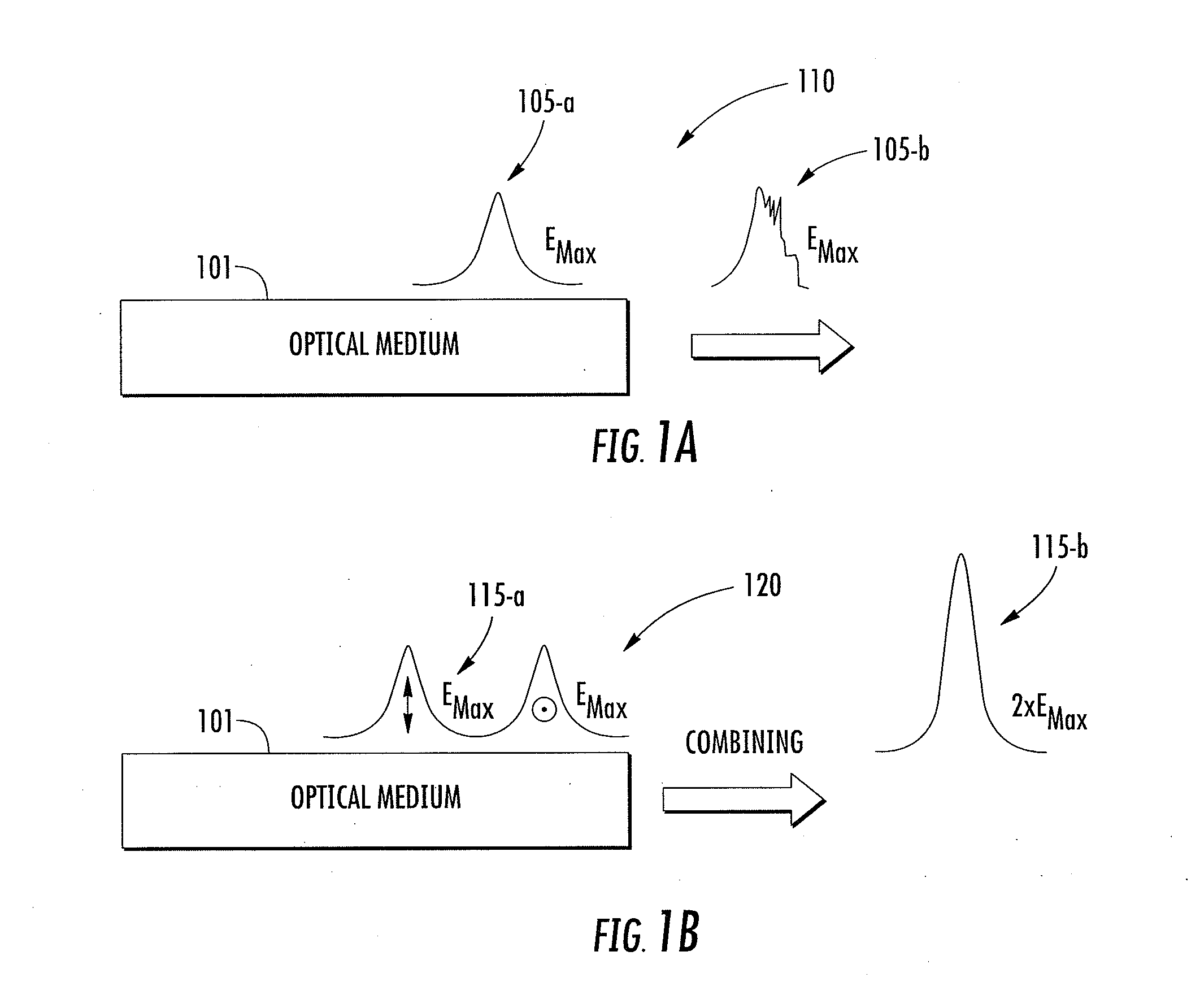
[0029]In at least one embodiment the available average output power of an amplifier is increased without substantial increase of pulse energy.

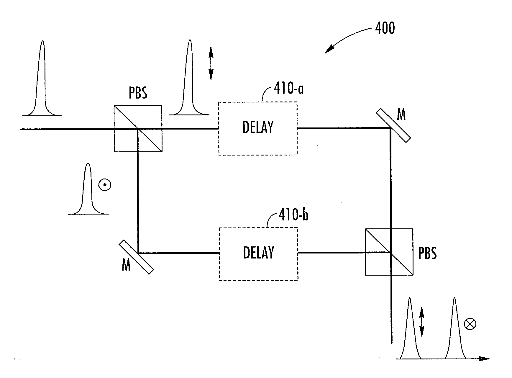
[0030]In at least one embodiment one pulse is split into a pair of pulses, each having a different polarization state. A relative delay between the polarization split pulses is generated and temporally separates the pulses during propagation in a medium, for example a passive optical material or an active, amplifying gain medium. In some embodiments the pulses may separate, at least in part, during amplification in a gain medium.

[0031]Some pulsed laser sources, such as fiber laser amplifiers utilizing PM fibers, preserve the polarization states. When excitation is sufficient, each polarization state can independently propagate in the laser source.

[0032]By way of example, FIGS. 1a and 1b compare pulse propagation 110 in a medium of a conventional laser system with propagation 120 of time separated pulses in accordance with one implementation of...


PUM


Abstract

In at least one embodiment time separated pulse pairs are generated, followed by amplification to increase the available peak and/or average power. The pulses are characterized by a time separation that exceeds the input pulse width and with distinct polarization states. The time and polarization discrimination allows easy extraction of the pulses after amplification. In some embodiments polarization maintaining (PM) fibers and/or amplifiers are utilized which provides a compact arrangement. At least one implementation provides for seeding of a solid state amplifier or large core fiber amplifier with time delayed, polarization split pulses, with capability for recombining the time separated pulses at an amplifier output. In various implementations suitable combinations of bulk optics and fibers may be utilized. In some implementations wavelength converted pulse trains are generated. A method and system of the present invention can be used in time domain applications utilizing multiple beam paths, for example spectroscopy.

Description

FIELD OF THE INVENTION[0001]The invention relates to methods and systems for generating laser pulses with high average power or high peak power, and is particularly applicable to time-domain spectroscopy such as pump-probe or terahertz measurement, where multiple beams carrying pulse trains are to be utilized, or where average power and / or pulse energy can be provided without undesirable nonlinear effects.BACKGROUND[0002]Utilization of pulsed laser sources has increased in industrial and scientific applications. In particular, applications of ultrashort laser technology have increased over the last few years in metrology, imaging and material processing applications. Fiber-based ultrashort systems are now well established for numerous applications, and are particularly well suited for high repetition rate applications at low-medium pulse energy. However, in either passive or gain fiber, the peak power of the amplified pulse is constrained because of the pulse distortion and signal s...

Claims


Application Information

Patent Timeline
IPC IPC(8): H01S3/067H01S3/091
CPCH01S3/0057H01S3/06712H01S3/2308H01S3/0092H01S3/302H01S3/10061H01S3/2383H01S3/091H01S3/067
Inventor XU, JINGZHOUCHO, GYU CHEON
Owner IMRA AMERICA
Why Eureka
Try Eureka