Sensor detection circuit, drive control circuit board, electronic equipment and air conditioner

A detection circuit and sensor technology, which is applied in the field of sensor detection circuit, drive control circuit board, electronic equipment and air conditioner, can solve the problems of low pressure accuracy and failure to meet pressure control accuracy requirements, etc.

Pending Publication Date: 2021-12-31
HEFEI MIDEA HEATING & VENTILATING EQUIP +1
View PDF0 Cites 0 Cited by
  • Summary
  • Abstract
  • Description
  • Claims
  • Application Information

AI Technical Summary

Problems solved by technology

[0003] Usually, the solution of pressure measurement is to obtain the output pressure of the sensor according to the relationship between the sampled value of the output voltage of the pressure sensor and the output voltage of the pressure sensor, and the relationship between

Method used


Image

  • Sensor detection circuit, drive control circuit board, electronic equipment and air conditioner
  • Sensor detection circuit, drive control circuit board, electronic equipment and air conditioner
  • Sensor detection circuit, drive control circuit board, electronic equipment and air conditioner

Examples


Embodiment 1

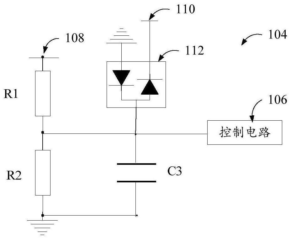
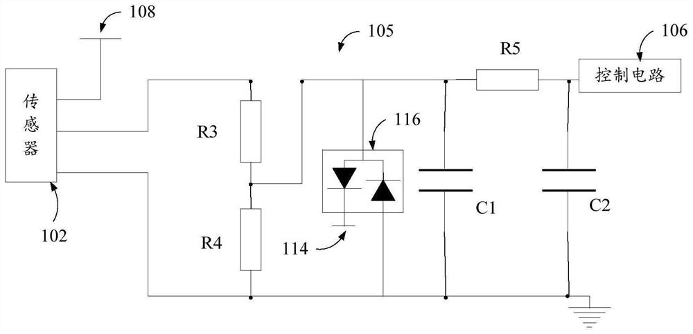
[0069] Such as figure 1 and figure 2 As shown, according to the first aspect of the present invention, the present invention provides a sensor detection circuit, including a sensor 102, a first sampling circuit 104, a second sampling circuit 105 and a control circuit 106, wherein the first sampling circuit 104, Be connected with the input voltage end of sensor 102, be used for collecting the input voltage of sensor 102; The second sampling circuit 105, be connected with the output voltage end of sensor 102, be used for collecting the output voltage of sensor 102; And control circuit 106 is respectively connected with the first The sampling circuit 104 is connected to the output terminal of the second sampling circuit 105 for outputting the detection result according to the collected output voltage of the sensor and the input voltage of the sensor.

[0070] The embodiment of the present application proposes a sensor detection circuit, wherein, compared with the existing embod...

Embodiment 2

[0123] In one embodiment, the present invention provides a driving and controlling circuit board, wherein the driving and controlling circuit board includes the sensor detection circuit according to any one of the above.

[0124] In this embodiment, since the drive control circuit board is provided with a sensor detection circuit as any of the above, the drive control circuit board has all the beneficial technical effects of the sensor detection circuit as any of the above, as compared with the existing In an embodiment, the sensor detection circuit can improve the detection accuracy of the detection result output by the sensor 102, so that the sensor detection circuit can adapt to use scenarios that require higher detection result accuracy.

[0125] Since the input voltage of the sensor 102 and the output voltage of the sensor 102 above are sampled by the first sampling circuit 104 and the second sampling circuit 105, the input voltage of the sensor 102 above is actually a sam...

Embodiment 3

[0129] In one embodiment, the present invention provides an electronic device, wherein the electronic device includes the sensor detection circuit according to any one of the above.

[0130] In this embodiment, since the electronic device is provided with a sensor detection circuit as any one of the above, the electronic device has all the beneficial technical effects of the sensor detection circuit as any one of the above, as compared with the existing embodiments, The sensor detection circuit can improve the detection accuracy of the detection result output by the sensor 102, so that the sensor detection circuit can be adapted to use scenarios requiring higher detection result accuracy.

[0131] Since the input voltage of the sensor 102 and the output voltage of the sensor 102 above are sampled by the first sampling circuit 104 and the second sampling circuit 105, the input voltage of the sensor 102 above is actually a sampling value of the input voltage, and the sensor The ...


PUM


Abstract

The invention provides a sensor detection circuit, a drive control circuit board, electronic equipment and an air conditioner, and the sensor detection circuit comprises a sensor, a first sampling circuit connected with the input voltage end of the sensor and used for collecting the input voltage of the sensor, a second sampling circuit connected with the output voltage end of the sensor and used for collecting the output voltage of the sensor, and a control circuit connected with the output end of the first sampling circuit and the output end of the second sampling circuit and used for outputting a detection result according to the collected output voltage of the sensor and the collected input voltage of the sensor. Compared with an existing technical scheme, the sensor detection circuit can improve the detection precision of the detection result output by the sensor; therefore, the sensor detection circuit can adapt to a use scene with a higher detection result precision requirement.

Description

technical field [0001] The invention relates to the field of control circuits, in particular to a sensor detection circuit, a drive control circuit board, electronic equipment and an air conditioner. Background technique [0002] Existing HVAC equipment usually uses pressure sensors to measure pressure. [0003] Usually, the solution of pressure measurement is to obtain the output pressure of the sensor according to the relationship between the sampled value of the output voltage of the pressure sensor and the output voltage of the pressure sensor, and the relationship between the output pressure of the sensor and the output voltage of the sensor. Those skilled in the art find that the existing pressure measurement The precision of the pressure measured by this method is not high, and it cannot meet the scene of high pressure control precision. Contents of the invention [0004] The present invention aims to solve at least one of the technical problems existing in the pri...

Claims


Application Information

Patent Timeline
IPC IPC(8): G01L19/00G01L11/00
CPCG01L19/00G01L11/00
Inventor 袁玉良
Owner HEFEI MIDEA HEATING & VENTILATING EQUIP
Why Eureka
Try Eureka