Check patentability & draft patents in minutes with Patsnap Eureka AI!

Non-coated optical laser reflector array assembly and laser ranging system

A technology of laser reflection and array components, which is applied in the direction of optical components, optics, instruments, etc., can solve problems such as instability, insufficient number of reflectors, and scarce data in ranging blind areas, so as to improve uniformity, solve data scarcity and Effects of Instability Problems

Pending Publication Date: 2021-12-31
11TH RES INST OF CHINA ELECTRONICS TECH GROUP CORP
View PDF0 Cites 0 Cited by
  • Summary
  • Abstract
  • Description
  • Claims
  • Application Information

AI Technical Summary

Problems solved by technology

[0010] Embodiments of the present invention provide a non-coated optical laser reflector array assembly and a laser ranging system, which improve and improve the uniformity of the separated diffraction beam ring through a reasonable spatial arrangement, and further compensate and solve the problems caused by the insufficient number of reflectors and the separation angle. The amount of data in the ranging blind area caused by too large is scarce and unstable

Method used


Image

  • Non-coated optical laser reflector array assembly and laser ranging system
  • Non-coated optical laser reflector array assembly and laser ranging system
  • Non-coated optical laser reflector array assembly and laser ranging system

Examples


Embodiment Construction

[0033] Exemplary embodiments of the present disclosure will be described in more detail below with reference to the accompanying drawings. Although exemplary embodiments of the present disclosure are shown in the drawings, it should be understood that the present disclosure may be embodied in various forms and should not be limited by the embodiments set forth herein. Rather, these embodiments are provided for more thorough understanding of the present disclosure and to fully convey the scope of the present disclosure to those skilled in the art.

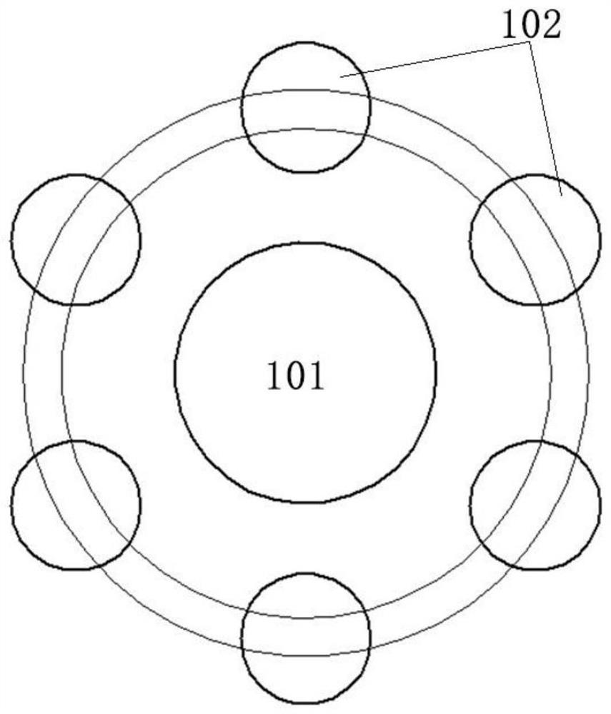
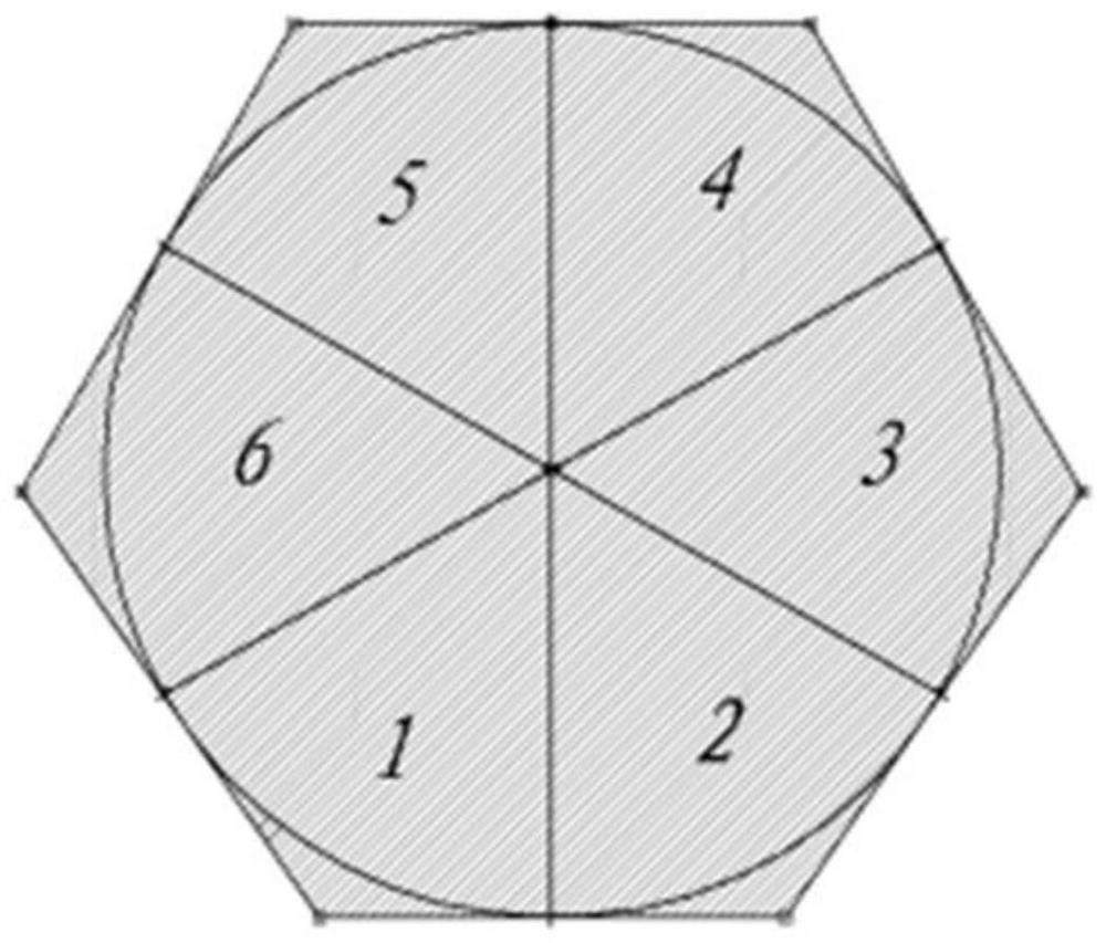
[0034] An embodiment of the present invention provides a non-coated optical laser reflector array assembly, including a plurality of polarization space laser reflectors, the far-field spot shapes of the emitted laser light from the polarization space space laser reflectors overlap periodically at a first angle, and the The first angle is determined according to the reflection surface angle of the polarization state spatial laser ref...


PUM


Abstract

The invention discloses a non-coated optical laser reflector array assembly, which comprises a plurality of polarization state space laser reflectors, far-field light spot forms of laser emitted by the polarization state space laser reflectors are periodically overlapped at intervals of a first angle, and the first angle is determined according to the angles of reflecting surfaces of the polarization state space laser reflectors; and according to a target structure, the installation azimuth angles of the polarization state space laser reflectors and the angle interval determined by the first angle and the number of the polarization state space laser reflectors, the polarization state space laser reflectors are arranged. According to the embodiment of the invention, the uniformity of the separated diffracted beam ring is improved through a reasonable spatial arrangement mode, and the problems of rare and unstable data volume of a ranging blind area caused by insufficient number of reflectors and overlarge separation angle are further compensated and solved.

Description

technical field [0001] The invention relates to the technical field of laser ranging, in particular to a non-coated optical laser reflector array assembly and a laser ranging system. Background technique [0002] In the field of aerospace, the laser reflector is a necessary component for tracking and measuring the distance of satellites and aerospace vehicles. It is a passive optical device and is mounted on the surface of the aircraft. In order to realize the long-distance precision measurement between the ranging point and the aircraft. In addition, it is also widely used in the precision measurement of objects such as long-distance targets. [0003] As a traditional laser reflector, its working technical status (divergence angle, maximum inclination angle, effective emission area, emissivity, far-field diffraction spot, velocity aberration compensation, etc.) is determined by the characteristics of the reflector (shape, size, angular error) Determining, for example, the...

Claims


Application Information

Patent Timeline
IPC IPC(8): G02B5/122
CPCG02B5/122
Inventor 吕华昌陈念江钟声远
Owner 11TH RES INST OF CHINA ELECTRONICS TECH GROUP CORP
Features
  • R&D
  • Intellectual Property
  • Life Sciences
  • Materials
  • Tech Scout
  • Unparalleled Data Quality
  • Higher Quality Content
  • 60% Fewer Hallucinations
Learn More