Redundancy control method, device and system, computer equipment and storage medium

A redundant control and controller technology, applied in the field of redundant control, to avoid conflicts, realize non-interference redundant switching, and ensure system stability and security

Pending Publication Date: 2021-12-31
GREE ELECTRIC APPLIANCES INC
View PDF10 Cites 6 Cited by
  • Summary
  • Abstract
  • Description
  • Claims
  • Application Information

AI Technical Summary

Problems solved by technology

[0005] Embodiments of the present invention provide a redundant control method, device, system, computer equipment, and storage media to at least solve the problem of how to realize hot switching without interference and difference in software redundant controllers in the prior art

Method used


Image

  • Redundancy control method, device and system, computer equipment and storage medium
  • Redundancy control method, device and system, computer equipment and storage medium
  • Redundancy control method, device and system, computer equipment and storage medium

Examples


Embodiment 1

[0054] This embodiment provides a redundant control method. The controller involved is a software redundant programmable controller. The master and slave of the controller can be set by software or hardware. Specifically, the hardware can be controlled by For example, if the DIP switch is set to 1, it means that the controller is a slave, and if the DIP switch is set to 0, it means that the controller is a master; the software method can be issued by the host computer to the controller. The controller will store the identity indication data in the configuration command. When the controller is started, by reading the identity indication data, it can know whether the controller is a master or a slave.

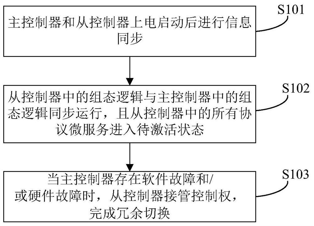
[0055] figure 1 is a flow chart of the redundancy control method provided by Embodiment 1 of the present invention, such as figure 1 As shown, the method includes the following steps:

[0056] S101, the master controller and the slave controller perform information synchronizat...

Embodiment 2

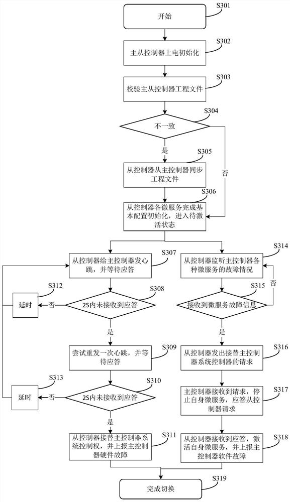
[0082] The above redundant switching method will be described below in conjunction with a specific embodiment. However, it should be noted that this specific embodiment is only for better illustrating the present application, and does not constitute an improper limitation to the present application. Explanations of terms that are the same as or corresponding to those in the foregoing embodiments will not be repeated in this embodiment.

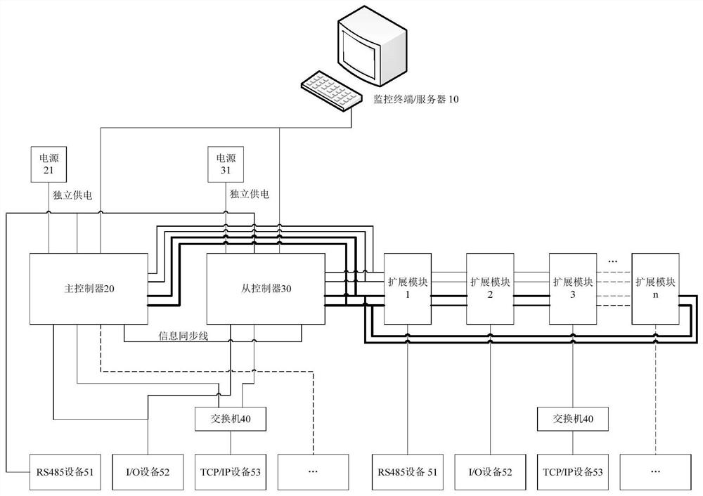
[0083] Such as figure 2 As shown, it is a schematic diagram of the architecture of the redundant control system. The redundant control system is divided into a three-layer structure of "management platform-controller-protocol equipment". Taking the building control system as an example, the system mainly includes: monitoring terminal / server 10 (equivalent to on the host computer), software redundant programmable controller (namely the main controller 20 and slave controller 30), controller dedicated expansion modules (namely the expansion mod...

Embodiment 3

[0122] Based on the same inventive concept, this embodiment provides a redundant control device, which can be used to implement the redundant control method described in the above embodiments. The device can be realized by software and / or hardware. The device can be applied in a controller.

[0123] Figure 9 is a structural block diagram of the redundant control device provided in Embodiment 3 of the present invention, as shown in Figure 9 As shown, the device includes:

[0124] Synchronization module 91, used for performing information synchronization after the controller is powered on and started;

[0125]The control module 92 is used to control the configuration logic in the slave controller to run synchronously with the configuration logic in the master controller when the controller is used as a slave controller, and to control all the configuration logic in the slave controller The protocol microservice enters the pending activation state;

[0126] The switchover ...


PUM


Abstract

The invention discloses a redundancy control method, device and system, computer equipment and a storage medium. The method comprises the following steps of: information synchronization is executed after the master controller and the slave controller are electrified and started; then the configuration logic of the slave controller and the configuration logic of the master controller operate synchronously, and all protocol micro-services in the slave controller enter a to-be-activated state; and when the master controller has a software fault and / or a hardware fault, the slave controller takes over the control right to complete redundancy switching. According to the invention, after the master and slave controllers are powered on and started, information synchronization is carried out, so that guarantee is provided for undifferentiated switching; wherein the configuration logic of the slave controller and the configuration logic of the master controller run synchronously, and the protocol micro-service in the slave controller enters a to-be-activated state to block the request, so that the shared bus conflict is avoided under the condition that the master and slave configuration logic is synchronous, and undifferentiated and interference-free redundancy switching is realized; therefore, no matter whether the main controller has a software fault or a hardware fault, the slave controller takes over the control right and switches in time, so that the stability and safety of the system are ensured.

Description

technical field [0001] The present invention relates to the technical field of redundancy control, in particular to a redundancy control method, device, system, computer equipment and storage medium. Background technique [0002] In the building automation system, failures of equipment, communication and software during operation are inevitable problems. The traditional method is to hire specific technicians to perform periodic maintenance on the system and replace old equipment regularly. In application scenarios with high requirements for reliability and safety, the building automation system must have relevant emergency plans for such failures to ensure that the control system does not go down and allow system maintenance without downtime. These functions are realized through software redundancy or hardware redundancy technology. [0003] The software redundancy system is usually realized by master-slave controllers, one for backup, and the device bus generally requires ...

Claims


Application Information

Patent Timeline
Patent Type & Authority Applications(China)
IPC IPC(8): G05B9/03
CPCG05B9/03
Inventor 牟桂贤陈楚洪申伟刚康宇涛李丽强
Owner GREE ELECTRIC APPLIANCES INC
Why Eureka
Try Eureka