
Electric power grounding pile for electric power engineering

A technology of electric power engineering and grounding piles, which is applied in the field of electric power engineering, can solve the problems of being unable to determine the grounding depth of charging piles, difficult to control the grounding effect, and easy to be pulled out, etc., to achieve diversified functions, convenient wiring, and improved grasping The effect of soil force

Active Publication Date: 2021-12-31
FUSHUN POWER SUPPLY COMPANY OF STATE GRID LIAONING ELECTRIC POWER SUPPLY +1
View PDF1 Cites 0 Cited by
  • Summary
  • Abstract
  • Description
  • Claims
  • Application Information

AI Technical Summary

Problems solved by technology

[0003] In the prior art, such as authorized announcement number CN 212033266 U discloses a fixed and stable electric grounding pile, including a vertically arranged electric grounding pile body, and a plurality of vertically arranged fixing rods are fixedly connected to the bottom end surface of the fixed disc , a plurality of said fixing rods are arranged around the periphery of the power grounding pile body. This technology makes the power grounding pile body hammered into the ground, and cooperates with the fixing rods to be more stable; the above-mentioned technology has the following defects: the fixing rods are smooth rods inserted into the ground Finally, the grounding pile can only be stabilized from the side direction. However, when the grounding pile is subjected to pulling force, it is still easy to be pulled out, which is not strong enough, and the above-mentioned technology cannot determine the depth of the charging pile grounding, and it is difficult to control the grounding effect. Therefore, , the present invention proposes a kind of electric power ground pile for electric engineering to solve the problems existing in the prior art

Method used


Image

  • Electric power grounding pile for electric power engineering
  • Electric power grounding pile for electric power engineering
  • Electric power grounding pile for electric power engineering

Examples


Embodiment 1

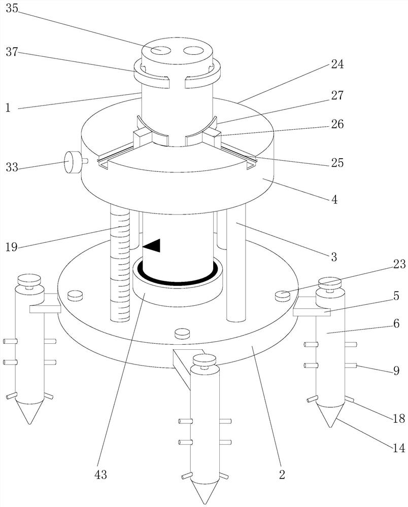
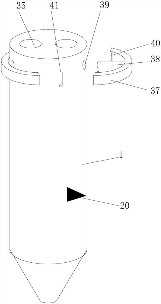
[0033] according to figure 1 , 2 , 3, 5, and 6, the present embodiment proposes a power grounding pile for power engineering, including a pile body 1 and a fastening frame, the pile body 1 is installed on the inside of the fastening frame, and the fastening frame Including a base 2, a pole 3 and a clamping assembly 4, the pole 3 is arranged on the top of the base 2, the clamping assembly 4 is arranged above the pole 3, and a support arm 5 is installed on the outside of the base 2, And the outer side of the support arm 5 is provided with a ground insertion tube 6;

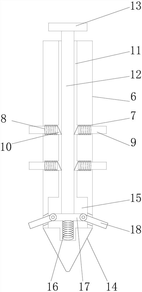
[0034] The inside of the side wall of the ground insertion tube 6 is provided with a slide hole 7, and the inside of the slide hole 7 is provided with a first spring 8, and the inside of the first spring 8 is provided with a poke bar 9, and the outer end of the poke bar 9 Connected to the ground insertion cylinder 6, the inner end of the poking rod 9 is provided with a triangular block 10, and the triangular block...

Embodiment 2

[0040] according to figure 1 , 2 , 3, and 4, this embodiment proposes a power grounding pile for electric power engineering, including a pile body 1 and a fastening frame, the pile body 1 is installed on the inner side of the fastening frame, and the fastening frame includes a base 2. The pole 3 and the clamping assembly 4, the pole 3 is arranged on the top of the base 2, the clamping assembly 4 is arranged above the pole 3, the outside of the base 2 is equipped with a support arm 5, and the support The outer side of the arm 5 is provided with a ground insertion tube 6;

[0041] The inside of the side wall of the ground insertion tube 6 is provided with a slide hole 7, and the inside of the slide hole 7 is provided with a first spring 8, and the inside of the first spring 8 is provided with a poke bar 9, and the outer end of the poke bar 9 Connected to the ground insertion cylinder 6, the inner end of the poking rod 9 is provided with a triangular block 10, and the triangula...

Embodiment 3

[0044] according to figure 1 , 2 , 7, this embodiment proposes a power grounding pile for electric power engineering, including a pile body 1 and a fastening frame, the pile body 1 is installed on the inner side of the fastening frame, and the fastening frame includes a base 2, The pole 3 and the clamping assembly 4, the pole 3 is arranged on the top of the base 2, the clamping assembly 4 is arranged above the pole 3, the outside of the base 2 is equipped with a support arm 5, and the support arm 5 The outer side is provided with the ground socket 6;

[0045] The inside of the side wall of the ground insertion tube 6 is provided with a slide hole 7, and the inside of the slide hole 7 is provided with a first spring 8, and the inside of the first spring 8 is provided with a poke bar 9, and the outer end of the poke bar 9 Connected to the ground insertion cylinder 6, the inner end of the poking rod 9 is provided with a triangular block 10, and the triangular block 10 is connec...


PUM


Abstract

The invention provides an electric power grounding pile for electric power engineering, which relates to the technical field of electric power engineering. The electric power grounding pile comprises a pile body and a fastening frame, the pile body is installed on the inner side of the fastening frame, the fastening frame comprises a base, a supporting rod and a clamping assembly, the supporting rod is arranged on the top of the base, and the clamping assembly is arranged above the supporting rod. A supporting arm is installed on the outer side of the base, and a ground inserting cylinder is arranged on the outer side of the supporting arm. A sliding hole is formed in the side wall of the ground inserting cylinder. The pile body is inserted into the base and the inner side of the clamping assembly, during installation, a ground inserting cylinder is inserted into the ground, then the pile body penetrates through the inner side of a fastening frame to be inserted into the ground, the pile body is locked in cooperation with the clamping assembly, in the process, through the action of the ground inserting cylinder, a threaded rod is inserted into a threaded inner groove, the threaded rod jacks up a triangular block in the inserting process, the poking rod is pushed to extend out of the ground inserting cylinder and is fixed in soil, so that the pile body is stabilized and cannot be influenced by side force, road holding force is provided, and the poking rod cannot be pulled out and is more reliable.

Description

technical field [0001] The invention relates to the technical field of electric power engineering, in particular to an electric grounding pile for electric power engineering. Background technique [0002] Grounding refers to the neutral point of the power system and electrical devices, the exposed conductive parts of electrical equipment and the conductive parts outside the device are connected to the earth through conductors, and can be divided into working grounding, lightning protection grounding and protective grounding. Ground piles refer to ground piles, support piles, and construction piles of buildings that can be used as ground-level piles. Power transmission lines and related equipment are mostly located outdoors, and are prone to lightning strikes. Line trips caused by lightning strikes often occur. In order to prevent lightning strikes, it is necessary to install grounding devices for transmission lines to guide the current generated by lightning strikes to the g...

Claims


Application Information

Patent Timeline
Patent Type & Authority Applications(China)
IPC IPC(8): H01R4/66
CPCH01R4/66
Inventor 曲永强刘志勇李秀婷
Owner FUSHUN POWER SUPPLY COMPANY OF STATE GRID LIAONING ELECTRIC POWER SUPPLY
Learn More