Direct cooling of a power converter by using a stamped plate

A technology for converters and cooling fluids, which is applied in the field of converters and can solve problems such as volume limitations and reduced output

Pending Publication Date: 2021-12-31
AUDI AG +1
View PDF1 Cites 0 Cited by
  • Summary
  • Abstract
  • Description
  • Claims
  • Application Information

AI Technical Summary

Problems solved by technology

However, the maximum possible volume of the molding material is usually limited when molding
This volume limit is exceeded when three semiconductor modules are combined
Furthermore, if all semiconductor chips are mounted on a unique substrate prior to testing, this can lead to a significant reduction in yield due to defective chips or connections

Method used


Image

  • Direct cooling of a power converter by using a stamped plate
  • Direct cooling of a power converter by using a stamped plate
  • Direct cooling of a power converter by using a stamped plate

Examples


Embodiment Construction

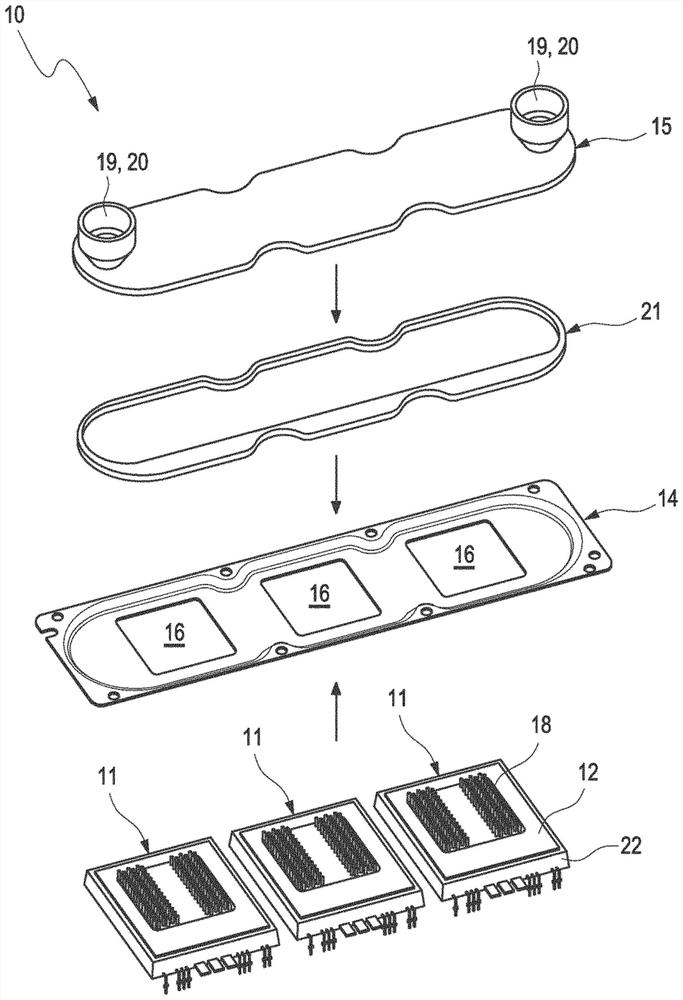
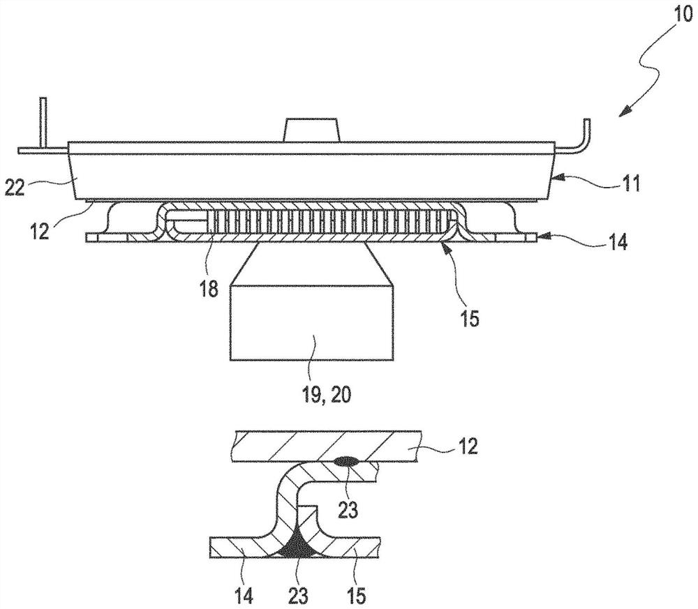
[0040] figure 1 An exploded perspective view showing the structure of the converter 10 according to the invention. Three semiconductor modules 11 are shown, each having a base 22 and a substrate 12 . Cooling fins 18 are formed on the base plate 12 . Three semiconductor modules 11 are mounted in a common receiving plate 14 , wherein receiving plate 14 has recesses 16 corresponding to the number of semiconductor modules 11 . The cutouts 16 are each configured to accommodate the semiconductor modules 11 in such a way that cooling fins 18 are arranged in the cutouts 16 .

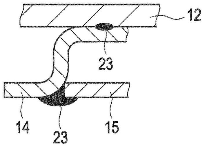
[0041] The three semiconductor modules 11 are each soldered to the receiving plate 14 in respective connection regions formed around the recesses 16 . The receiving plate 14 is provided for receiving the bypass flow breaker 21 . The bypass flow breaker 21 can optionally be arranged in the receiving plate 14 .

[0042] The flow-through interrupter 21 is designed as an enclosure surrounding the semiconductor ...


PUM


Abstract

The present invention relates to a power converter (10) comprising a semiconductor module (11) with a base plate (12) and comprising a cooling housing (13), wherein the cooling housing (13) comprises a receiving plate (14) and a cover (15), wherein the receiving plate (14) has a cutout (16), wherein the receiving plate (14) is connected to the base plate (12) of the semiconductor module (11) around the cutout (16), wherein the cover (15) is connected to the receiving plate (14) along a closure path around the cutout (16), wherein either the receiving plate (14) or the cover (15) takes the form of a stamped or deep-drawn plate. Furthermore, the present invention relates to methods for producing a power converter (10) according to one of the preceding features.

Description

technical field [0001] The invention relates to a converter comprising a cooling housing and at least one semiconductor module with a base plate. Background technique [0002] The proliferation of electric vehicles places high demands on the performance and cost of power semiconductor modules used in electric powertrains. For semiconductor modules, this means in particular the continuous improvement of the trend towards higher operating temperatures and higher power densities. [0003] One possible way of extending the permissible operating temperature to a higher level could be to replace the conventional potting of the upper surface of the semiconductor module by injection molding. In this case, the injection-molded module can have a base plate, which is held in the molding compound / encapsulation compound. For optimal cooling, heat dissipation structures can be integrated directly in the substrate, wherein the heat dissipation structures are in contact with the cooling f...

Claims


Application Information

Patent Timeline
Patent Type & Authority Applications(China)
IPC IPC(8): H05K7/20
CPCH05K7/20927H01L23/473
Inventor T·格拉丁格尔A·阿佩斯迈尔B·泽恩勒D·托雷辛
Owner AUDI AG
Why Eureka
Try Eureka