
Tree transplanting device for forestry field

A tree and field technology, which is applied in the field of tree transplanting devices, can solve the problems that the roots and leaves of trees cannot be sprayed, and achieve the effects of preventing low survival rate, avoiding waist injury, and alleviating work intensity

Inactive Publication Date: 2022-01-04
陈荣早
View PDF0 Cites 0 Cited by
  • Summary
  • Abstract
  • Description
  • Claims
  • Application Information

AI Technical Summary

Problems solved by technology

[0003] The purpose of the present invention is to at least solve one of the technical problems in the prior art, and provide a tree transplanting device used in the forestry field, which can solve the problem of effectively fixing the trees and not being able to spray the roots and leaves of the trees question

Method used


Image

  • Tree transplanting device for forestry field
  • Tree transplanting device for forestry field
  • Tree transplanting device for forestry field

Examples


Embodiment 1

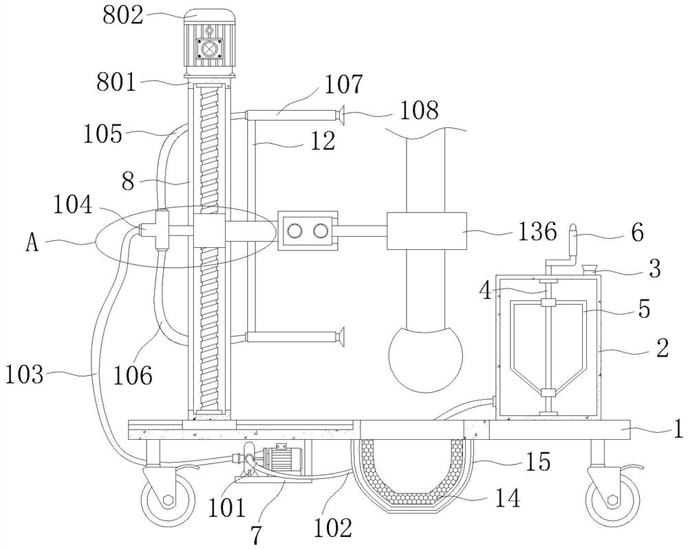
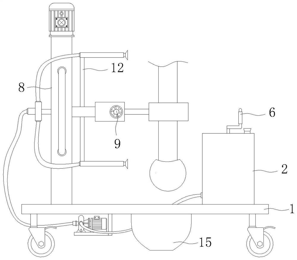
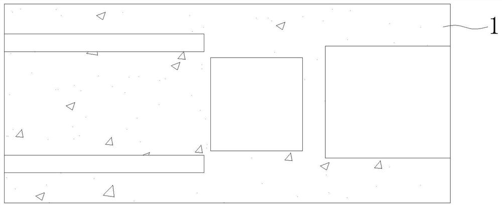
[0033] see Figure 1-6 , the present invention provides a technical solution: a tree transplanting device used in the forestry field, comprising a bottom plate 1, a moving mechanism 8, a spraying mechanism 10 and a clamping mechanism 13, the top of the bottom plate 1 is fixedly connected with a water tank 2, and the bottom of the bottom plate 1 The bottom is fixedly connected with the L-shaped plate 7, the top of the bottom plate 1 is provided with two sets of first openings, and the electric slide rails are slidably installed in the first openings. The moving mechanism 8 includes a fixed plate 801, a motor 802, a threaded rod 803, and a first guide. Rod 804, fixing block 805 and connecting plate 806, the spraying mechanism 10 includes a water pump 101, a first water pipe 102, a water outlet pipe 103, a tee pipe 104, a first connecting pipe 105, a second connecting pipe 106, a liquid storage chamber 107 and a spray head 108 , the clamping mechanism 13 includes a mounting plate...

Embodiment 2

[0037] see Figure 1-6 , on the basis of the first embodiment, the bottom of the fixed plate 801 is fixedly connected with a sliding seat, the sliding seat is slidably installed inside the electric sliding rail, the fixing plate 801 is slidably installed with the electric sliding rail, and the top of the fixing plate 801 is fixedly connected with the motor 802 , the interior of the fixed plate 801 is provided with a first slot, the output shaft of the motor 802 is fixedly connected with a threaded rod 803 through a coupling, the threaded rod 803 is rotatably installed inside the first slot, and the inside of the first slot is fixedly installed There are two sets of first guide rods 804, the outer wall of the threaded rod 803 is threadedly connected with a fixing block 805, the fixing block 805 is slidably sleeved on the outer walls of the two sets of first guide rods 804, and one side of the fixing block 805 is fixedly connected with a connection Plate 806, both sides of the f...


PUM


Abstract

The invention discloses a tree transplanting device for the forestry field, and relates to the technical field of forestry. The tree transplanting device for the forestry field comprises a bottom plate, a moving mechanism, a spraying mechanism and a clamping mechanism, a water tank is fixedly connected with the top of the bottom plate, an L-shaped plate is fixedly connected with the bottom of the bottom plate, and the moving mechanism comprises a fixing plate, a motor, a threaded rod, a first guide rod, a fixing block and a connecting plate. The spraying mechanism comprises a water pump, a first water pipe, a water outlet pipe, a three-way pipe, a first connecting pipe, a second connecting pipe, a liquid storage cavity and a spray head, and the clamping mechanism comprises a mounting plate, a second guide rod, a bidirectional threaded rod, a supporting plate, a first clamping plate and a second clamping plate. According to the tree transplanting device, trees can be effectively fixed and clamped, the phenomenon that the trees incline in the transportation process is prevented, the transplanted trees can be sprayed, tree roots and tree leaves of the trees can be sprayed, and the trees are further maintained in the transportation process.

Description

technical field [0001] The invention relates to the technical field of forestry, in particular to a tree transplanting device used in the field of forestry. Background technique [0002] Transplanting trees can increase the green area of ​​the city, which is an important means to protect the ecological balance of the city. The existing part of the tree transplanting device has poor fixing effect and cannot effectively fix the trees, resulting in damage to the trees. The tree transplanting device cannot spray the roots and leaves of the trees, which leads to the evaporation of tree water and the loss of tree nutrients, which has a certain impact on the survival rate of tree transplants. SUMMARY OF THE INVENTION [0003] The purpose of the present invention is to solve at least one of the technical problems existing in the prior art, and to provide a tree transplanting device used in the forestry field, which can effectively fix the trees and cannot spray the roots and leave...

Claims


Application Information

Patent Timeline
IPC IPC(8): A01G23/04A01C23/04A01G29/00
CPCA01G23/043A01G23/04A01C23/047A01G29/00
Inventor 陈荣早朱玉粉王艳华
Owner 陈荣早
Learn More