
Anti-overheating self-lubricating bearing seat

A self-lubricating, bearing seat technology, applied in the direction of bearing components, shafts and bearings, engine lubrication, etc., can solve the problems of increasing the wear degree of bearing seats and bearings, dusty, complicated operation, etc., to reduce looseness and ensure normal operation. effect of work

Inactive Publication Date: 2022-01-04
响水县瑞丰重型轴承座制造有限公司
View PDF0 Cites 0 Cited by
  • Summary
  • Abstract
  • Description
  • Claims
  • Application Information

AI Technical Summary

Problems solved by technology

[0003] However, in the actual use of traditional bearing seats, in order to prevent excessive wear and high temperature of the bearings and bearing seats, cooling lubricating oil is generally added to the bearing seats on a regular basis, but most of the bearing seats are mostly used in actual operation. It is necessary to open the shell of the bearing seat, and then use suitable lubricating oil to lubricate the inside of the bearing seat, which is more cumbersome and inconvenient during operation; , some mechanical vibration is unavoidable, and during the long-term vibration process, the mounting bolts on the housing of the bearing housing may become loose, which may affect the normal operation of the bearing; in addition, when used in some large machinery During equipment, sometimes there will be more dust, which is easy to adhere to the bearing seat, especially after lubrication, it is very easy to adhere to the lubricating fluid, and the bearing seat and bearing are high-precision parts. After too much dust, it may increase the degree of wear of the bearing seat and bearing during operation

Method used


Image

  • Anti-overheating self-lubricating bearing seat
  • Anti-overheating self-lubricating bearing seat
  • Anti-overheating self-lubricating bearing seat

Examples


Embodiment Construction

[0026] In order to make the technical means, creative features, goals and effects achieved by the present invention easy to understand, the present invention will be further described below in conjunction with specific embodiments.

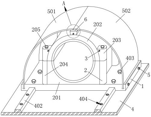
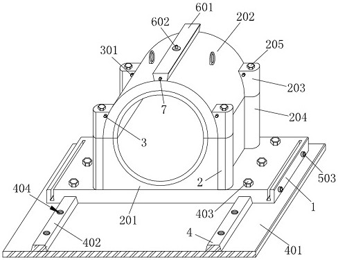
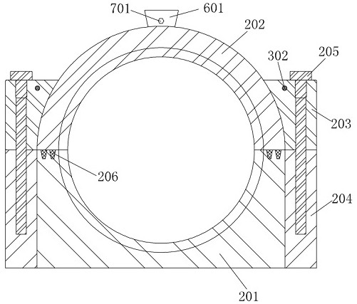
[0027] Such as Figure 1-Figure 7 As shown, a self-lubricating bearing housing for preventing overheating according to the present invention includes a bottom plate 1, on which a main body mechanism 2 is provided, and a fastening mechanism 3 is arranged inside the main body mechanism 2, and on the bottom plate 1 A placement mechanism 4 is provided, a protective mechanism 5 is provided on the bottom plate 1, a storage mechanism 6 is provided on the main body mechanism 2, and a lubrication mechanism 7 is provided on the storage mechanism 6;

[0028] The main body mechanism 2 includes a lower casing 201, the bottom plate 1 is fixedly connected with the lower casing 201, and the lower casing 201 is provided with an upper casing 202;

[0029] The stor...


PUM


Abstract

The invention relates to the technical field of bearing seats, in particular to an anti-overheating self-lubricating bearing seat. The anti-overheating self-lubricating bearing seat comprises a bottom plate, wherein a main body mechanism is arranged on the bottom plate, a fastening mechanism is arranged in the main body mechanism, a placement mechanism is arranged on the bottom plate, a protection mechanism is arranged on the bottom plate, a storage mechanism is arranged on the main body mechanism, and a lubricating mechanism is arranged on the storage mechanism. Through the cooperation of the storage mechanism and the lubricating mechanism, the interior of the bearing seat can be automatically and quantitatively lubricated at any time conveniently during operation, and a mounting shell of the bearing seat does not need to be disassembled; the fastening mechanism is arranged in the main body mechanism, so that a fastening effect on a mounting bolt on a bearing seat shell is conveniently achieved, and the situation that the mounting bolt is loosened due to vibration is reduced; the protection mechanism is arranged on the bottom plate, so that the main body mechanism is conveniently shielded and protected, dust attached to the main body mechanism is reduced, and the abrasion degree of the main body mechanism and a bearing in a running process is reduced.

Description

technical field [0001] The invention relates to the technical field of bearing seats, in particular to a self-lubricating bearing seat for preventing overheating. Background technique [0002] The bearing seat is a supporting component used to fix the bearing. The bearing seat and the bearing are an important part of the mechanical equipment. Its main function is to support the mechanical rotating body, reduce the friction coefficient during its movement, and ensure its rotation accuracy. The bearing needs to be installed in the bearing seat for use. The inner support point of the bearing is the shaft, and the outer support is often called the bearing seat. [0003] However, in the actual use of traditional bearing seats, in order to prevent excessive wear and high temperature of the bearings and bearing seats, cooling lubricating oil is generally added to the bearing seats on a regular basis, but most of the bearing seats are mostly used in actual operation. It is necessar...

Claims


Application Information

Patent Timeline
IPC IPC(8): F16C35/00F16N1/00
CPCF16C35/00F16N1/00
Inventor 汪加平杨伟香杨红香杨胜景杨泽香
Owner 响水县瑞丰重型轴承座制造有限公司
Learn More