Supercharge Your Innovation With Domain-Expert AI Agents!

Rotating part test displacement monitoring device

A technology of displacement monitoring and rotating parts, applied in measuring devices, electrical devices, instruments, etc., can solve the problems of complex adjustment, prolonged test period, small adjustable range, etc. wide effect

Pending Publication Date: 2022-01-04
AECC AVIATION POWER CO LTD
View PDF7 Cites 0 Cited by
  • Summary
  • Abstract
  • Description
  • Claims
  • Application Information

AI Technical Summary

Problems solved by technology

At present, the displacement monitoring of the wheel disc test carried out on the vertical rotation tester is monitored by using the sensor bracket and related accessories to fix the eddy current sensor. There are some shortcomings. The position of the measurement point is determined by the sensor bracket and related accessories, which is rigid. Fixed, the adjustable range is small, the adjustment is complicated, and manual adjustment is required, the radial position error of the measuring point is ±5mm, and the accuracy is low
In addition, during the test process, the axial displacement of the measurement point has a large range of changes, while the measurement range of the eddy current sensor is small, the sensor cannot always be within the optimal monitoring range, and the equipment needs to be stopped frequently for adjustment. The vertical rotation tester is a large tester, and the equipment is prepared A long time will lead to prolongation of the test period and affect the progress of the test
In addition, the measurement point can only perform single-point measurement, and cannot realize multi-point monitoring

Method used


Image

  • Rotating part test displacement monitoring device
  • Rotating part test displacement monitoring device
  • Rotating part test displacement monitoring device

Examples


Embodiment Construction

[0025] The present invention will be further described in detail below in conjunction with specific embodiments, which are explanations of the present invention rather than limitations.

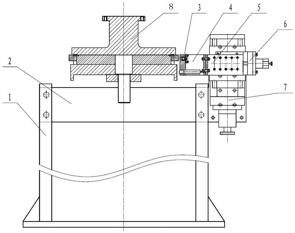
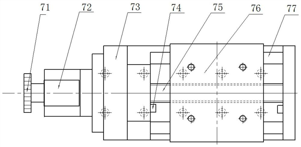
[0026] The fixed bracket 1 is an I-shaped structure, the lower end is connected to the ground by bolts, and there is a row of mounting holes on both sides of the upper end, which are connected to the L-shaped support plate 2 through the mounting holes, and the height of the transverse support plate can be adjusted by selecting mounting holes of different heights. There are 6 symmetrical light holes on the short side of the L-shaped support plate 2, and the light holes are connected to the base of the vertical mobile platform assembly 7 by bolts. The vertical mobile platform assembly is composed of a manual adjustment end 71, a stepping motor 72, a platform base 73, a limit device 74, a high-precision screw 75, a movable platform 76, and a guide rail 77. The platform base 73 is fixedly connecte...


PUM


Abstract

The invention discloses a rotating part test displacement monitoring device. The device comprises a fixing support, a supporting plate, an eddy current displacement sensor, a transverse moving platform assembly and a vertical moving platform assembly; and the fixing support is fixedly connected with the supporting plate, the supporting plate is fixedly connected with the vertical moving platform assembly, the vertical moving platform assembly is provided with the transverse moving platform assembly, and the transverse moving platform assembly is fixedly connected with the eddy current displacement sensor. By means of the transverse moving platform assembly and the vertical moving platform assembly, a detection point of the eddy current displacement sensor is moved; by controlling a stepping motor pulse signal of the moving platform assembly, a movable platform on the moving platform assembly is controlled to move accurately; and by adjusting the transverse position of the eddy current displacement sensor, free switching monitoring of multiple measuring points in a wheel disc testing process is achieved, and it is always guaranteed that the measuring points are within the measuring range of the eddy current displacement sensor.

Description

technical field [0001] The invention belongs to the technical field of aero-engine testing, in particular to a displacement monitoring device for a rotating part test. Background technique [0002] Aeroengine rotor strength test is an important method for the analysis and evaluation of its design strength and life. Due to the high-speed rotation of the tested part, displacement measurement is a technical difficulty in the test. At present, the displacement monitoring of the wheel disc test carried out on the vertical rotation tester is monitored by using the sensor bracket and related accessories to fix the eddy current sensor. There are some shortcomings. The position of the measurement point is determined by the sensor bracket and related accessories, which is rigid. Fixed, the adjustable range is small, the adjustment is complicated, and manual adjustment is required, the radial position error of the measuring point is ±5mm, and the accuracy is low. In addition, during ...

Claims


Application Information

Patent Timeline
IPC IPC(8): G01B7/02
CPCG01B7/02
Inventor 赵飞蔡婉花李宇苗向薛明吴生让李季
Owner AECC AVIATION POWER CO LTD
Features
  • R&D
  • Intellectual Property
  • Life Sciences
  • Materials
  • Tech Scout
  • Unparalleled Data Quality
  • Higher Quality Content
  • 60% Fewer Hallucinations
Learn More