A method and device for monitoring an igbt drive overcurrent fault

A technology for overcurrent faults and monitoring devices, which is applied to measuring devices, measuring electricity, and measuring electrical variables, etc., and can solve problems such as low reliability

Active Publication Date: 2021-05-18
XUJI GRP +3
View PDF15 Cites 0 Cited by
  • Summary
  • Abstract
  • Description
  • Claims
  • Application Information

AI Technical Summary

Problems solved by technology

[0007] The purpose of the present invention is to provide a method and device for monitoring an IGBT-driven overcurrent fault to solve the problem of low reliability in the prior art when only one overcurrent alarm signal is reported for each overcurrent fault alarm interval

Method used


Image

  • A method and device for monitoring an igbt drive overcurrent fault
  • A method and device for monitoring an igbt drive overcurrent fault
  • A method and device for monitoring an igbt drive overcurrent fault

Examples


Embodiment Construction

[0026] In order to make the object, technical solution and advantages of the present invention clearer, the present invention will be further described in detail below in conjunction with the accompanying drawings and examples, but the embodiments of the present invention are not limited thereto.

[0027] Embodiment of the IGBT driving overcurrent fault monitoring method of the present invention:

[0028] The software and hardware involved in using this method include: IGBT driver program, IGBT upper-level control circuit equipment SCE and IGBT-driven overcurrent monitoring circuit. These are all existing technologies and will not be introduced too much.

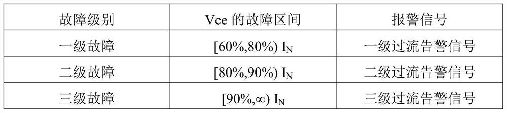
[0029] The voltage monitored by the overcurrent monitoring circuit is the voltage Vce between the collector and the emitter, and the k-level overcurrent fault alarm limit set in the program is Vce k (k=1,2,...), the set level X overcurrent alarm signal is FB X (X=1, 2, . . . ). i.e. at Vce 1 ≤Vce2 In the over-current fau...


PUM


Abstract

The invention relates to a method and device for monitoring an IGBT drive overcurrent fault. The method monitors the measured voltage between the collector and the emitter of the IGBT in real time; judges the fault level of the IGBT according to the measured voltage, and the corresponding fault level corresponds to a setting Within a fault level, each time the measured voltage is monitored to be in the voltage range corresponding to the fault level, an overcurrent alarm signal corresponding to the fault level is issued, and at least two overcurrent alarm signals are issued. Under the condition of not changing the detection environment of hardware, the present invention processes the logic signal through software control, realizes the whole monitoring of the IGBT in the overcurrent fault alarm interval, and avoids the occurrence of false alarms in the traditional methods commonly used in the world. The reliability and accuracy of IGBT overcurrent fault detection are improved, and the invention has higher reference value.

Description

technical field [0001] The invention belongs to the technical field of power electronics, and in particular relates to a method and device for monitoring an IGBT drive overcurrent fault. Background technique [0002] Insulated Gate Bipolar Transistor (IGBT), as an emerging high-power electronic device, combines the high input impedance of Metal-Oxide-Semiconductor Field-Effect Transistor (MOSFET) and power transistor ( Giant Transistor, GTR) has the advantages of low conduction voltage drop, low driving power and low saturation voltage, so IGBT has been widely used in AC systems, such as AC motors, frequency converters, switching power supplies, lighting circuits, traction drives And other fields, especially in the field of high-voltage flexible DC transmission, IGBT is the core device of high-voltage and large-capacity flexible DC converters and high-voltage DC circuit breakers. [0003] IGBT has bidirectional switching characteristics, and its flow capacity determines the...

Claims


Application Information

Patent Timeline
Patent Type & Authority Patents(China)
IPC IPC(8): G01R31/26G01R19/165
CPCG01R19/16576G01R31/2601
Inventor 范彩云李娟洪波张志刚黄永瑞常忠廷张坤
Owner XUJI GRP
Why Eureka
Try Eureka