Camera shooting assembly with conductive slip ring structure

A technology of camera components and conductive slip rings, which is applied to the parts of color TVs, TV system parts, electrical components, etc., can solve the problems of being unable to bend and adjust the camera angle, affecting the efficiency of shooting, and unfavorable flipping, etc. Achieve the effect of good electrode connection, improve practicability, and ensure continuous work

Inactive Publication Date: 2022-01-04
CHONGQING THREE GORGES UNIV
View PDF2 Cites 0 Cited by
  • Summary
  • Abstract
  • Description
  • Claims
  • Application Information

AI Technical Summary

Problems solved by technology

[0003] When the camera assembly is in use, because the camera assembly is fixed in one direction for rotation, it is not conducive to flipping, and when shooting, because the ingested object is too high, the ingested object needs to be adjusted, which affects the shooting efficiency. Now The commonly used conductive slip ring structure is still mainly for the transformation and upgrading of cables. The cables that need to be rotated and bent are connected through the conductive slip ring structure, and the cable ends are still prone to fatigue disconnection during unlimited continuous rotation. phenomenon, the existing conductive slip ring structure can only perform rotational movement, and cannot be bent to adjust the camera angle, so there are certain defects;
[0004] CN109800844A in the prior patent technology relates to a bendable and rotatable U disk, which includes a U disk body, a usb plug and a connecting part in the U disk structure, including a conductive slip ring that provides rotation and bending, But this design can only be used in a small U disk connection part space; while CN20228506U needs to provide an outward bending power unit in other existing conductive slip ring assemblies that provide power to the camera, and in CN109044248A, it is realized by means of an outward snake bone assembly The camera assembly bends and rotates in the wall to shoot, so it is impossible to achieve rotation and bending while providing electrical connections

Method used


Image

  • Camera shooting assembly with conductive slip ring structure
  • Camera shooting assembly with conductive slip ring structure
  • Camera shooting assembly with conductive slip ring structure

Examples


Embodiment Construction

[0037] In order to make the object, technical solution and advantages of the present invention clearer, the present invention will be further described in detail below in combination with specific embodiments and with reference to the accompanying drawings. It should be noted that, in the case of no conflict, the embodiments of the present invention and the features in the embodiments can be combined with each other.

[0038] It is understood that these descriptions are exemplary only, and are not intended to limit the scope of the invention.

[0039] A camera assembly with a conductive slip ring structure provided by some embodiments of the present invention will be described below with reference to the accompanying drawings.

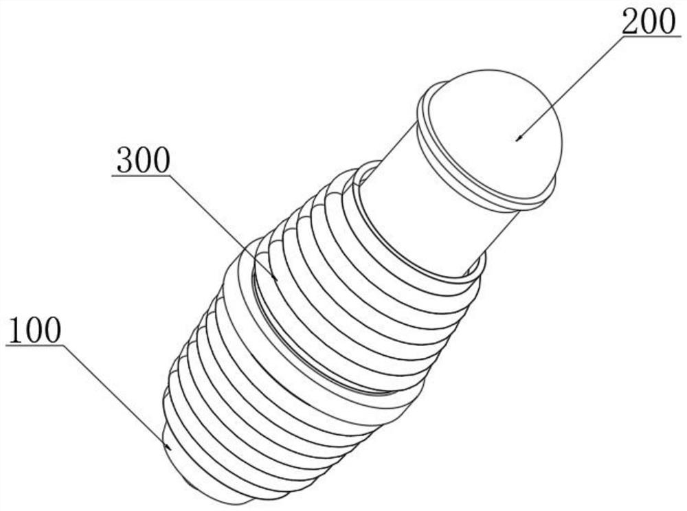
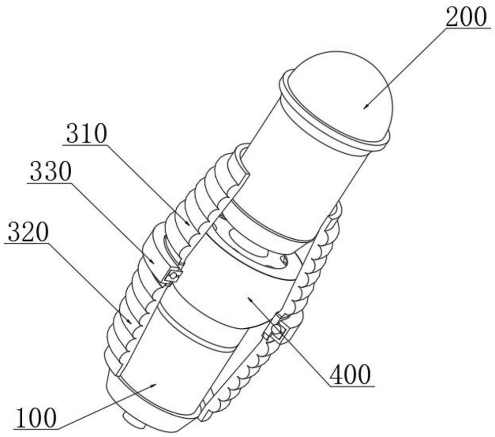
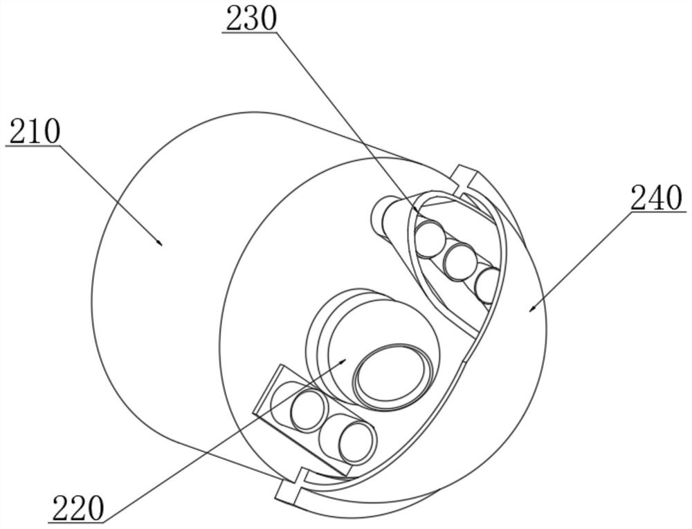
[0040] combine Figure 1-8 As shown, the present invention provides a camera assembly with a conductive slip ring structure, including: a positioning base rod 100, a camera mechanism 200, a limit movement set 300, and a rotating slide for connecting the...


PUM


Abstract

The invention discloses a camera shooting assembly with a conductive slip ring structure, and the camera shooting assembly comprises a positioning base rod, a camera shooting mechanism, a limiting movement sleeve group, and a rotary slip ring assembly which is used for connecting the positioning base rod and the camera shooting mechanism, the camera shooting mechanism comprises a camera shooting control end, and a camera and a light supplementing LED lamp group which are fixedly installed at one end of the camera shooting control end, and the end part of the camera shooting control end head is fixedly sleeved with a protective cover. According to the invention, the electrode contact strip is connected with the moving electrode of the static guide slip ring and the static contact guide groove is connected with the moving electrode of the contact electrode point so as to connect the direct connection contact of the signal end of the camera assembly, so that the electrode signal in the rotation or bending angle adjustment of the camera assembly is connected, and a traditional cable which is easy to break and damage is prevented from being adopted for connection; therefore, relative movement of the camera shooting assembly and unlimited continuous rotation movement of data signals are kept, the service life is long, and the electrode connection effect is good.

Description

technical field [0001] The invention relates to the technical field of conductive slip rings, in particular to a camera assembly with a conductive slip ring structure. Background technique [0002] The camera component is used to take pictures of objects and transmit them to external equipment for processing, while the conductive slip ring belongs to the application category of electrical contact sliding connection, which is specially used in the process of some unlimited continuous rotation, including the parts of the stator and rotor, respectively. Wires are connected and fixed, and can also be divided into different types according to some differences in the overall structure. The specific effects brought about by different types of products in the process of use are also completely different. The precision power transmission device that realizes the image, data signal and power transmission of two relative rotating mechanisms is suitable for unlimited continuous rotatio...

Claims


Application Information

Patent Timeline
Patent Type & Authority Applications(China)
IPC IPC(8): H01R39/08H01R39/64H04N5/225
CPCH01R39/08H01R39/643H04N23/00
Inventor 闫东方熊江冯玉明何春霖芦泽群
Owner CHONGQING THREE GORGES UNIV
Why Eureka
Try Eureka