
Optical fiber end face processing method and optical fiber connector

A technology for optical fiber end face processing and connectors, which is applied in the direction of optical waveguide coupling, grinding devices, grinding machine tools, etc., can solve problems such as poor cutting of optical fiber end faces, and achieve the effects of solving poor cutting, improving connection performance, and ensuring full docking

Active Publication Date: 2016-05-04
SHENZHEN EPLU SCI TECH
View PDF5 Cites 0 Cited by
  • Summary
  • Abstract
  • Description
  • Claims
  • Application Information

AI Technical Summary

Problems solved by technology

[0004] The technical problem to be solved by the present invention is to provide an optical fiber end face processing method and an optical fiber connector to effectively solve the problem of poor cutting of optical fiber end faces, facilitate full contact between optical fiber end faces, and improve optical fiber connection. Reduce the return loss value of the fiber optic connector and reduce the insertion loss value of the fiber optic connector

Method used


Image

  • Optical fiber end face processing method and optical fiber connector
  • Optical fiber end face processing method and optical fiber connector

Examples


Embodiment Construction

[0023] In order to have a clearer understanding of the technical features, purposes and effects of the present invention, the specific implementation manners of the present invention will now be described in detail with reference to the accompanying drawings.

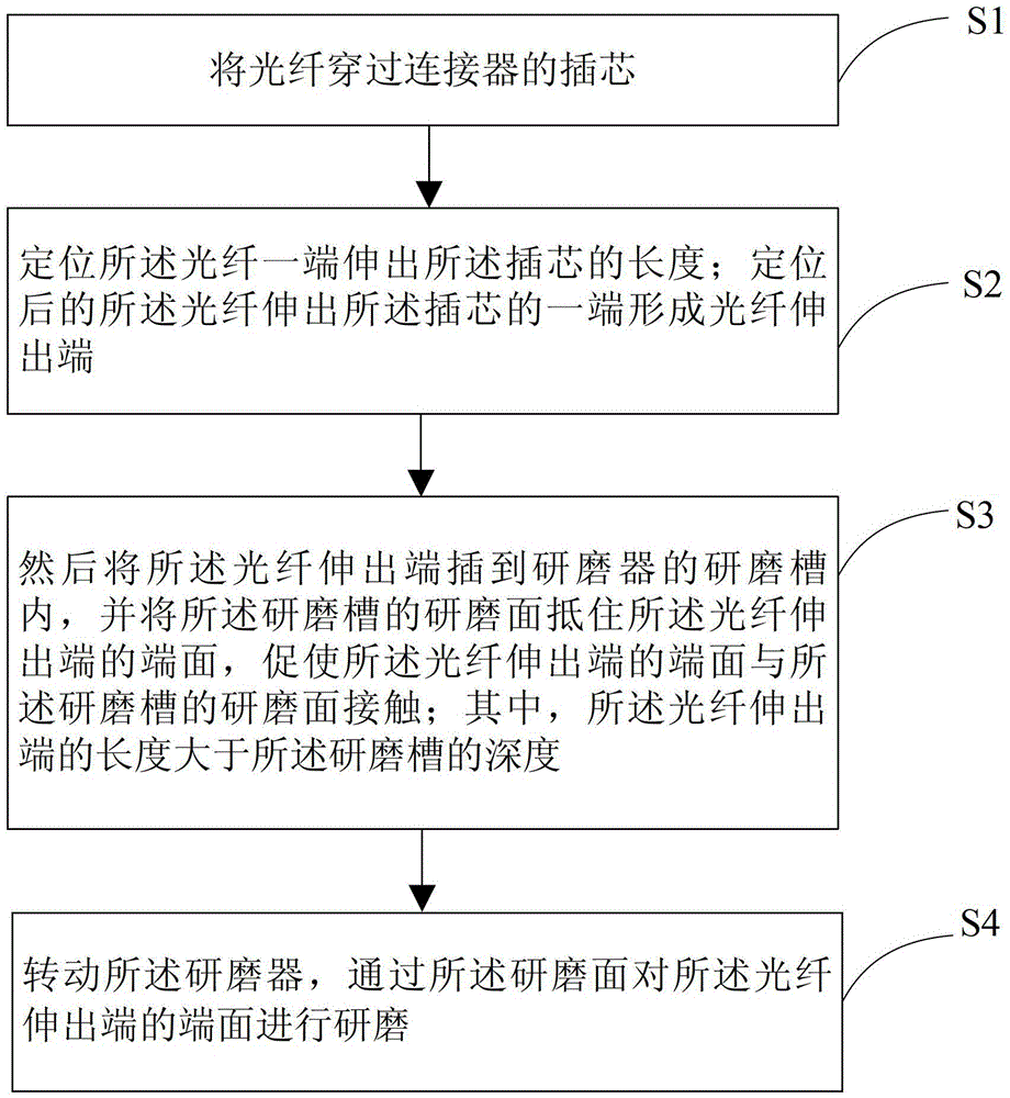
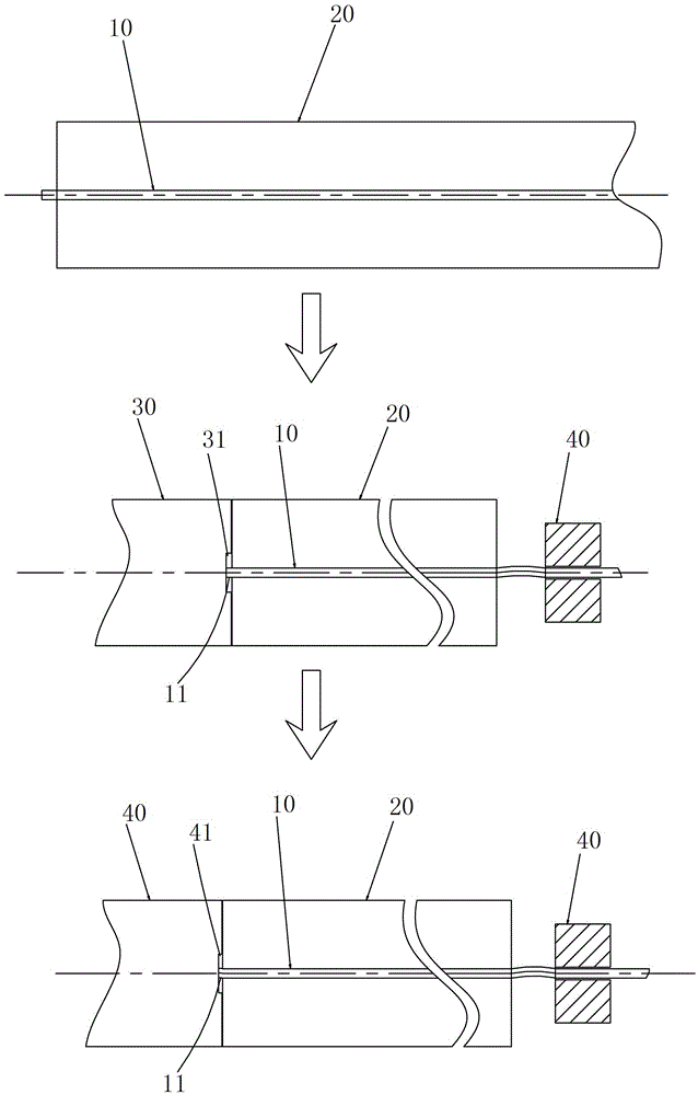
[0024] like figure 1 As shown, it is a schematic flow chart of an optical fiber end face processing method according to an embodiment of the present invention, combined with figure 2 , the optical fiber end face processing method comprises the following steps:

[0025] S1. Pass the optical fiber 10 through the ferrule 20 of the connector. Wherein, the optical fiber 10 is pre-cut to a fixed length, and then passed into the ferrule 20 after cutting. After the optical fiber 10 passes through the ferrule 20 , one end of the optical fiber 10 can extend out of the ferrule 20 , and the protruding length is preferably less than or equal to 10 mm. The ferrule 20 of the connector is a ceramic ferrule or a metal ferrule or the...


PUM


Abstract

The invention relates to an optical fiber end face processing method and an optical fiber connector. The method includes the steps of S1, penetrating an optical fiber through an insert core of the connector; S2, positioning length of one end, extending out of the insert core, of the optical fiber to form an extending end of the optical fiber; S3, inserting the extending end into a grinding groove of a grinder, using a grinding face of the grinding groove to abut the end face of the extending end to allow the end face to be in contact with the grinding face; S4, rotating the grinder, and grinding the end face of the extending end through the grinding face; wherein the length of the extending end is larger than the depth of the grinding groove. By the method, the problem of bad optical fiber end face cutting is solved, fully contact of optical fiber end faces is facilitated, return loss of the optical fiber connector is reduced, and insertion loss of the optical fiber connector is reduced.

Description

technical field [0001] The invention relates to an optical fiber processing method, in particular to an optical fiber end face processing method and an optical fiber connector. Background technique [0002] With the development of fiber-to-the-home, in order to cope with the complex and changeable terminal environment, wiring is carried out on site according to the actual situation of the terminal, and more and more fiber optic field connectors are used to connect to the home optical network. Optical fiber field connectors are roughly divided into two categories, one is the optical fiber field connector with embedded optical fiber, the field optical fiber is docked with the embedded optical fiber of this type of optical fiber field connector through the V-shaped groove; the other is the straight-through optical fiber On-site connector, the connector has only one optical node on the end face of the ceramic ferrule; during on-site assembly, the optical fiber is clamped in the ...

Claims


Application Information

Patent Timeline
Patent Type & Authority Patents(China)
IPC IPC(8): B24B37/10G02B6/38
Inventor 胡庆庆衷诚王七月
Owner SHENZHEN EPLU SCI TECH
Learn More