Corner laser device and fastener positioning device thereof

A technology of positioning device and angle adjustment device, which is applied in the direction of auxiliary devices, laser welding equipment, auxiliary welding equipment, etc., can solve the problems of low efficiency, large laser joint error on flat side, large joint error on flat side, etc., and achieve product uniformity Good, good connection effect, high efficiency effect

Pending Publication Date: 2018-11-09
ZHEJIANG WEIXING IND DEV
View PDF0 Cites 0 Cited by
  • Summary
  • Abstract
  • Description
  • Claims
  • Application Information

AI Technical Summary

Problems solved by technology

[0003] At present, the button surface laser technology is mostly plane laser and side laser technology. Taking the plane laser as an example, the button is laid flat on the fixture during production, and the product result is formed by laser scanning back and forth. After the completion, a preliminary semi-finished product is obtained. The button After washing, polishing, dry rolling or painting, the finished product can be obtained; it can be seen that the plane laser can only be carried out on a relatively horizontal plane, that is, the same plane. Correspondingly, the side laser can only be carried out on the side. When laser patterning, usually adopt the method of lasering on the plane first, then vertically locate the buttons and fix them with vertical and vertical fixtures, and then perform side lasering. Although this method can initially achieve the corner laser effect, it has low efficiency and large errors in the connection of flat side lasers. , poor uniformity and other issues, resulting in large product limitations and the inability to achieve mass production
[0004] Therefore, how to solve the problems of low laser efficiency at corners and large joint errors of flat sides is a technical problem that those skilled in the art need to solve at present.

Method used


Image

  • Corner laser device and fastener positioning device thereof
  • Corner laser device and fastener positioning device thereof
  • Corner laser device and fastener positioning device thereof

Examples


Embodiment Construction

[0025] The core of the present invention is to provide a button positioning device of a corner laser device, through which the corner laser of a button can be realized, and the efficiency is high, the effect of connecting flat sides is good, and the manufactured product has good uniformity. Another core of the present invention is to provide a corner laser device including the above button positioning device.

[0026] In order to enable those skilled in the art to better understand the solution of the present invention, the present invention will be further described in detail below in conjunction with the accompanying drawings and specific embodiments.

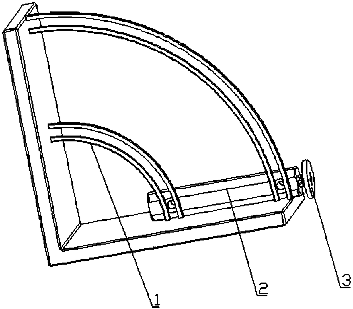
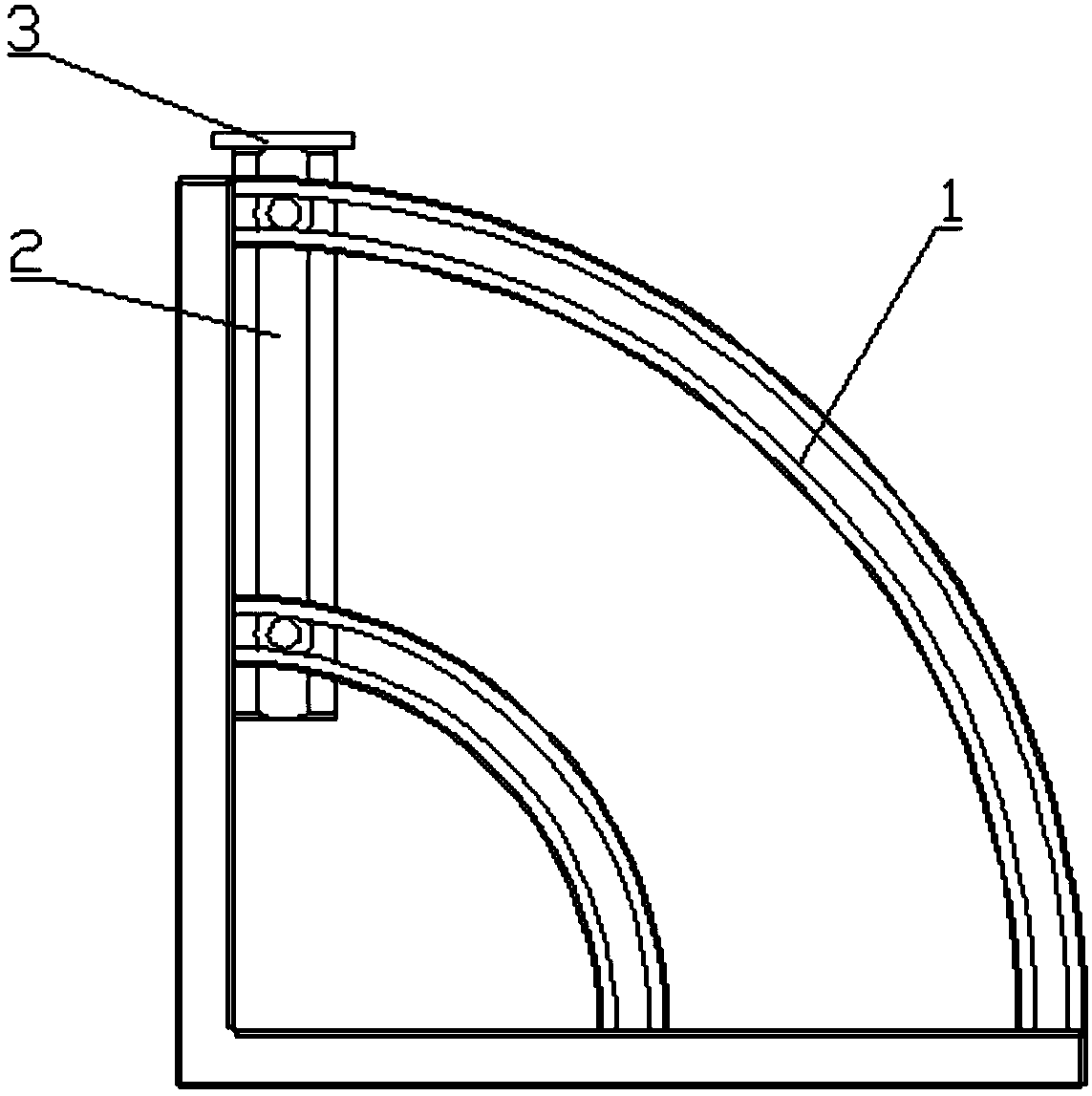
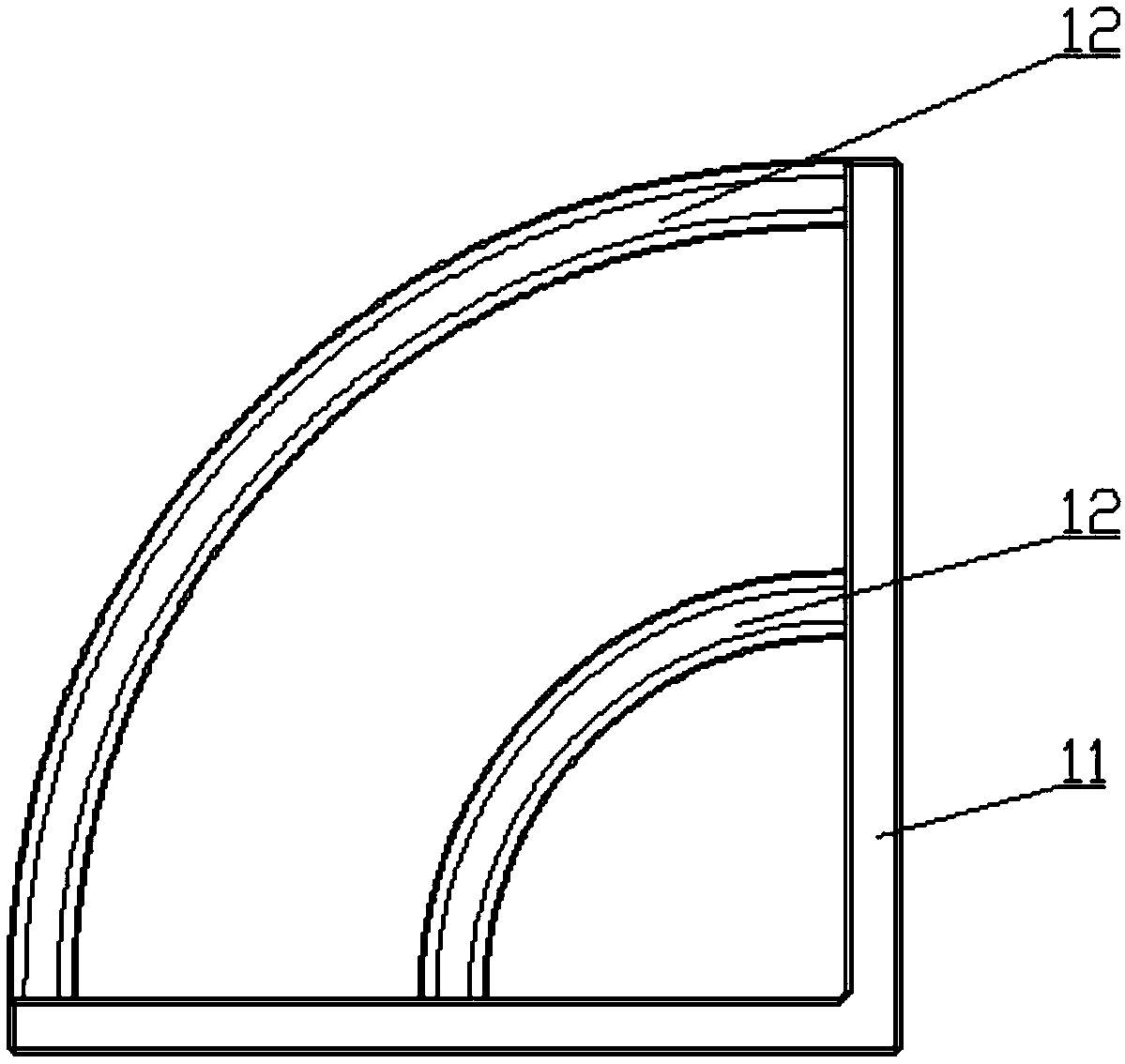
[0027] Please refer to Figure 1 to Figure 4 , figure 1 It is a structural schematic diagram of a specific embodiment of the button positioning device provided by the present invention; figure 2 It is a schematic diagram of a usage state of a specific embodiment of the button positioning device provided by the present inve...


PUM


Abstract

The invention discloses a corner laser device and a fastener positioning device thereof. The fastener positioning device comprises an angle adjusting device and a fastener fixing clamp, the angle adjusting device comprises a supporting frame and an arc-shaped sliding way arranged on the supporting frame, the fastener fixing clamp comprises a connecting rod with one end installed on the arc-shapedsliding way and a die head arranged at the other end of the connecting rod and used for being clamped into a fastener hole, the connecting rod can slide along the arc-shaped sliding way and generate plane rotation in the sliding process, the extending-out direction of the die head is parallel to the rotating plane of the connecting rod, in other words, a fastener can be driven to rotate when the connecting rod slides, and the corner laser effect can be achieved within the rotating scope; when corner laser patterns need to be manufactured, the fastener is fixed through the die head, then the corner effect of the patterns needing to be subjected to laser is used for adjusting the position of the fastener fixing clamp on the angle adjusting device, a laser machine is started for conducting laser on the front face and the side face of the fastener, the laser efficiency is high, the patterns on the front and side faces are good in joining effect, and the product uniformity is good.

Description

technical field [0001] The invention relates to the technical field of button processing, in particular to a button positioning device for a corner laser device. In addition, the present invention also relates to a corner laser device comprising the button positioning device. Background technique [0002] With the increase of leisure and decoration functions in the clothing accessories market, the surface laser technology has gradually formed a product effect feature, which can enrich the surface effect of the product. [0003] At present, the button surface laser technology is mostly plane laser and side laser technology. Taking the plane laser as an example, the button is laid flat on the fixture during production, and the product result is formed by laser scanning back and forth. After the completion, a preliminary semi-finished product is obtained. The button After washing, polishing, dry rolling or painting, the finished product can be obtained; it can be seen that the...

Claims


Application Information

Patent Timeline
IPC IPC(8): B23K26/352B23K26/08B23K37/04
CPCB23K26/0853B23K26/352B23K37/0443
Inventor 陈贤桥周斌
Owner ZHEJIANG WEIXING IND DEV
Why Eureka
Try Eureka