Combined use of air-oil separator and oil filter in systems requiring oil separation and filtration

An oil separator, filter technology, applied in the direction of dispersed particle filtration, separation method, dispersed particle separation, etc.

Inactive Publication Date: 2022-01-04
MIKROPOR MAKINA SANAYI VE TICARET ANONIM SIRKETI
View PDF6 Cites 0 Cited by
  • Summary
  • Abstract
  • Description
  • Claims
  • Application Information

AI Technical Summary

Problems solved by technology

[0007] There is a need to develop a system for addressing the problems associated with the known state of the art systems described above

Method used


Image

  • Combined use of air-oil separator and oil filter in systems requiring oil separation and filtration
  • Combined use of air-oil separator and oil filter in systems requiring oil separation and filtration
  • Combined use of air-oil separator and oil filter in systems requiring oil separation and filtration

Examples


Embodiment Construction

[0036] This invention relates to the operation of air-oil separators and oil filters used in systems requiring oil separation and filtration on a single block. In other words, the present invention discloses an oil separation and filtration system having an air-oil separator and an oil filter.

[0037] Thanks to the invention, energy losses are reduced and a more compact system is provided for use.

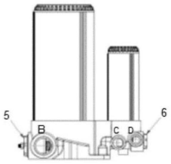
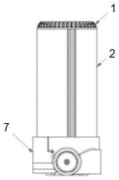
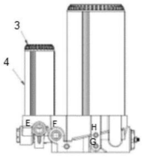
[0038] According to the system of the invention, the system basically comprises an air-oil separator element (27), an oil filter element (10), a minimum pressure valve (5), a temperature valve (6) and blocks connected to these components ( 7).

[0039] In the drawings of the present invention, Port A-Port G are provided.

[0040] The general principle of operation of the system according to the invention is as follows:

[0041] Air passes through port A ( Figure 1D ) into the air-oil separator section. An air-oil separator element (27) in the first housing (2) separates air ...


PUM

PropertyMeasurementUnit
thicknessaaaaaaaaaa

Abstract

The present invention relates to operation of air-oil separators and oil filters used in systems requiring oil separation and filtration on a single block. In other words, the present invention discloses an oil separation and filtration system having an air-oil separator and an oil filter.

Description

technical field [0001] This invention relates to the operation of air-oil separators and oil filters used in systems requiring oil separation and filtration on a single block. Background technique [0002] Oil separation and filtration systems are available for pressurized air compressors. [0003] Multiple blocks can be connected to the compressor respectively. Also, in most compressors, the oil filter and air-oil separator are connected separately. This situation leads to increased energy losses in the system. There is a need to develop a system that provides a solution to the problem of high energy loss due to the separate connection of the oil filter and the air-oil separator in the compressor. [0004] Furthermore, in air-oil separators and oil filters used in prior art compressors, sleeve pieces (also referred to as outer pieces) are glued to the bottom plate. This creates a risk of oil leakage and low pressure drag in the system. [0005] Furthermore, the oil fil...

Claims


Application Information

Patent Timeline
Patent Type & Authority Applications(China)
IPC IPC(8): B01D46/00
CPCB01D46/0031B01D46/2411B01D46/2414B01D46/0005B01D36/02B01D2265/026B01D2201/295B01D2201/4076B01D2201/4053B01D29/15B01D2201/24B01D46/0087
Inventor 易卜拉辛·凯末尔·雅兹茨
Owner MIKROPOR MAKINA SANAYI VE TICARET ANONIM SIRKETI
Why Eureka
Try Eureka