Medicine storage box automatic medicine taking machine
A medicine storage box and automatic technology, which is applied in the field of medicine dispensing machines, can solve the problems of inability to grasp Chinese medicinal materials by themselves, and achieve the effects of convenient quantitative storage and taking, easy maintenance, and ingenious overall structure.
- Summary
- Abstract
- Description
- Claims
- Application Information
AI Technical Summary
Problems solved by technology
Method used
Image

Examples
Embodiment Construction
[0031] The present invention will be described in further detail below in conjunction with specific embodiments.
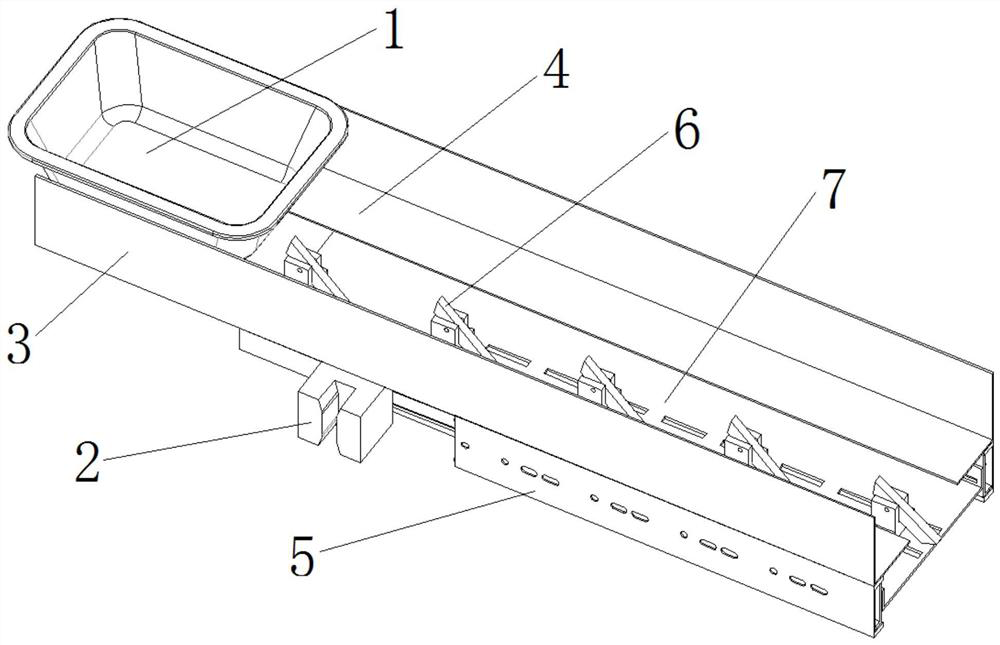
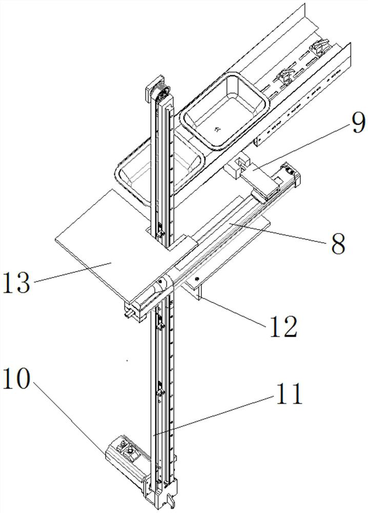
[0032] In the accompanying drawings of the present invention, 1 is a medicine storage box, 2 is a toggle block, 3 is a guard plate, 4 is a support plate, 5 is a guide rail, 6 is a push block, 7 is a push block installation plate, and 8 is an X-axis slide rail , 9 is a sliding block, 10 is a motor, 11 is a Y-axis slide rail, 12 is a motion platform, 13 is a medicine storage box supporting plate, and 14 is a medicine storage box pusher.
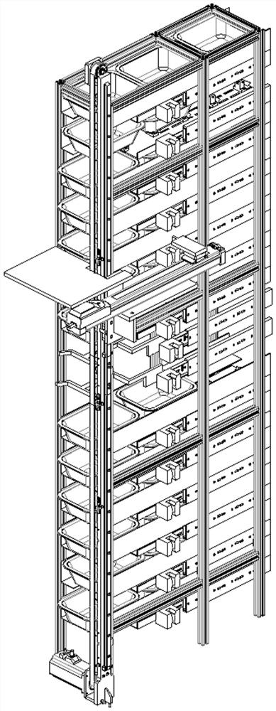
[0033] The invention relates to an automatic medicine taking machine for a medicine storage box, which specifically includes a medicine storage box, a driving mechanism, a frame and a unit module. The frame includes a vertical cubic frame, and horizontal and vertical reinforcing ribs are arranged on the left, right and upper sides of the cubic frame. The upper surface of the medicine storage box is open, so that bulk Chinese medic...
PUM
 Abstract
Description
Claims
Application Information
 - Generate Ideas
- Intellectual Property
- Life Sciences
- Materials
- Tech Scout
- Unparalleled Data Quality
- Higher Quality Content
- 60% Fewer Hallucinations
Browse by: Latest US Patents, China's latest patents, Technical Efficacy Thesaurus, Application Domain, Technology Topic, Popular Technical Reports.
© 2025 PatSnap. All rights reserved.Legal|Privacy policy|Modern Slavery Act Transparency Statement|Sitemap|About US| Contact US: help@patsnap.com