Electric wire pay-off device

A technology of pay-off device and wire, applied in transportation and packaging, cable laying equipment, transportation of filamentous materials, etc., can solve the problems of manual moving, pulling back to a place dozens of meters away, laborious

Pending Publication Date: 2022-01-07
中核华辰建筑工程有限公司
View PDF11 Cites 0 Cited by
  • Summary
  • Abstract
  • Description
  • Claims
  • Application Information

AI Technical Summary

Problems solved by technology

During the installation work, if a large cable enters the site, the manufacturer will bring a cable reel. Although it is not easy to move, it is easy to roll and use the cable rack to release the wire; but there is a very common headache for small cables and wires. If they are heavy, each person can hold a few coils, but it is very laborious to carry them or climb...

Method used


Image

  • Electric wire pay-off device
  • Electric wire pay-off device
  • Electric wire pay-off device

Examples


Embodiment Construction

[0023] The present invention will be described in further detail below in conjunction with the accompanying drawings.

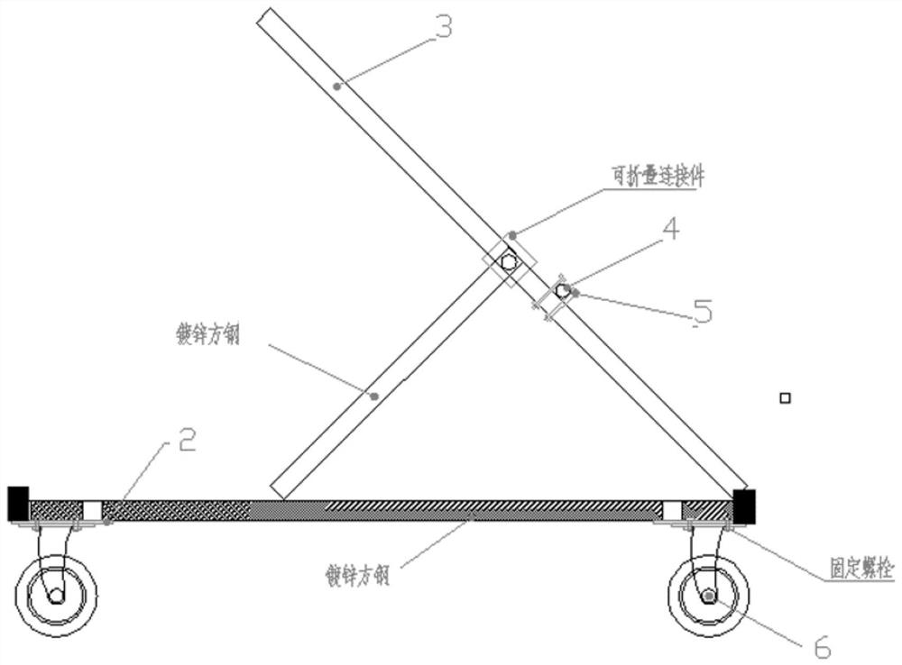
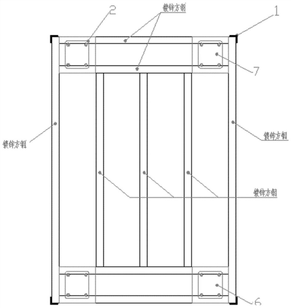
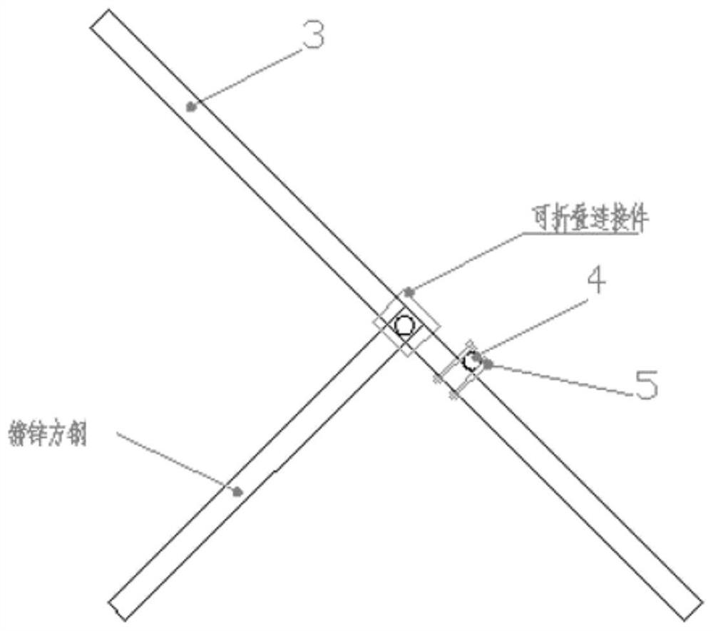
[0024] Such as Figure 1-Figure 4 Shown: a wire pay-off device, including angle steel 1, steel plate 2, galvanized square steel 3, galvanized steel pipe (thickened) 4, screw nut, directional wheel (with brake) 6, universal wheel (with brake) )7;

[0025] Angle steel 1 is welded to the four corners of the rectangular main frame to fix the pay-off device; steel plate 2 is welded to the four corners of the bottom side of the rectangular main frame to fix the wheels; galvanized square steel 3 is used to weld the entire The main frame and the frame of the pay-off device; the galvanized steel pipe (thickened) 4 is used on the pay-off device as the rotating bearing pressure tube of the winding reel, and is fixed by bolts; the bolt and nut 5 are used in the four main bracket The angled steel plate is used to fix the wheel, as well as the overlapping joint of the fo...


PUM


Abstract

The invention discloses an electric wire pay-off device. The electric wire pay-off device comprises a horizontally-arranged rectangular main body support, angle steel is arranged on the four corners of the rectangular main body support, steel plates are arranged on the four corners of the bottom side of the rectangular main body support, two directional wheels are arranged on one side of the bottom of each steel plate, two universal wheels are arranged on the other side of the bottom of each steel plate, a pay-off device frame is arranged in the position, located on the side of the directional wheels, of the top of the rectangular main body support, and galvanized square steel is arranged between the middle of the pay-off device frame and the middle of the rectangular main body support. The electric wire pay-off device has the characteristics of being multipurpose, time-saving and labor-saving.

Description

technical field [0001] The invention relates to the technical field of threading in pipes and laying wires in slot boxes, in particular to a wire releasing device. Background technique [0002] In most installation projects at present, there are two types of power supply wires usually placed, one is cable and the other is wire. During the installation work, if large cables enter the site, the manufacturer will bring a cable reel. Although it is not easy to move, it is still easy to roll and use the cable rack to release the wires; but there is a very common headache for small cables and wires. If they are heavy, each person can carry a few coils, but it is very laborious to carry them or climb stairs. After getting them to the field, one person needs to be dedicated to straighten the strings, and sometimes they have to pull the strings back and forth to dozens of times. There are also pay-offs on the market at a distance of one meter, but they are small in size and still ne...

Claims


Application Information

Patent Timeline
IPC IPC(8): B65H75/42B65H75/44B65H49/38H02G1/06
CPCB65H75/425B65H75/4465B65H49/38H02G1/06B65H2701/34
Inventor 冀志雄马阿庆高凤阳魏磊姚俊钦
Owner 中核华辰建筑工程有限公司
Why Eureka
Try Eureka