Textile operation equipment with thread layer carding structure

A technology for operating equipment and textiles, used in textiles and papermaking, spray/jet textile material treatment, fabric surface trimming, etc.

Inactive Publication Date: 2022-01-07
南通中邦丝织有限公司
View PDF11 Cites 2 Cited by
  • Summary
  • Abstract
  • Description
  • Claims
  • Application Information

AI Technical Summary

Problems solved by technology

"However, when the textiles in this device are combed in line layers, the miscellaneous hairs and other debris are easy to float in the air, which affects the effect of removing the miscellaneous hairs.

Method used


Image

  • Textile operation equipment with thread layer carding structure
  • Textile operation equipment with thread layer carding structure
  • Textile operation equipment with thread layer carding structure

Examples


Embodiment 1

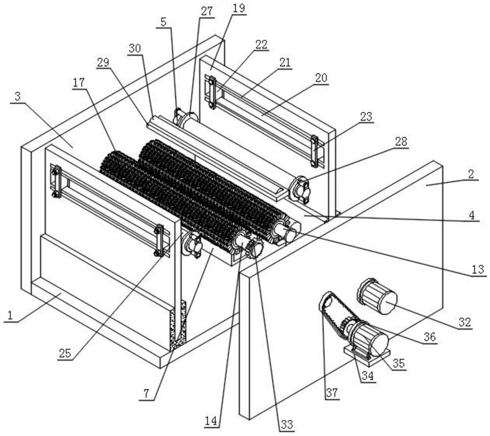
[0043] Such as figure 2 , image 3 with Figure 4 As shown, a textile operation equipment with a line layer carding structure includes a base plate 1, a front plate 2, a rear plate 3, a U-shaped insert plate 4, a traction roller 5 and a fixed plate 6, and the front and back sides of the base plate 1 are respectively equipped with Front panel 2 and rear panel 3;

[0044] Specifically, the bottom plate 1 provides a relatively stable installation position for the components on the top, and is convenient to integrate the various components on the top, so that it is combined into a complete line layer carding structure. The bottom plate 1, the front plate 2 and the rear plate 3 three The latter is the outer frame of the textile handling equipment.

[0045] Two sets of U-shaped insert plates 4 arranged side by side are installed on the top of the bottom plate 1, and two sets of traction rollers 5 arranged side by side are installed on the front of the rear plate 3, and the front...

Embodiment 2

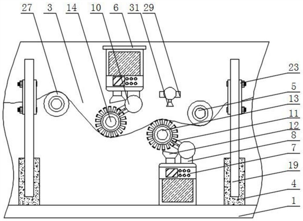
[0050] Such as figure 1 , Figure 5 with Image 6 As shown, the front of the front plate 2 is installed with the first roller 13 and the second roller 14, and the second roller 14 is located obliquely above the first roller 13, and the backs of the first roller 13 and the second roller 14 run through the back plate 3, the outer surfaces of the first roller 13 and the second roller 14 are equipped with threaded sleeves 15, and the outer surfaces of the two sets of threaded sleeves 15 are fitted with connecting cylinders 16 through thread fitting, and the outer surfaces of the connecting cylinders 16 are uniformly installed with The brush rod 17, the tail end of the brush rod 17 is equipped with multiple groups of evenly arranged arc-shaped protrusions 18.

[0051] Concretely, the first rotating roller 13 and the second rotating roller 14 can rotate under the drive of the motor, and then drive the threaded sleeve 15 installed on its outer surface, the connecting cylinder 16 an...

Embodiment 3

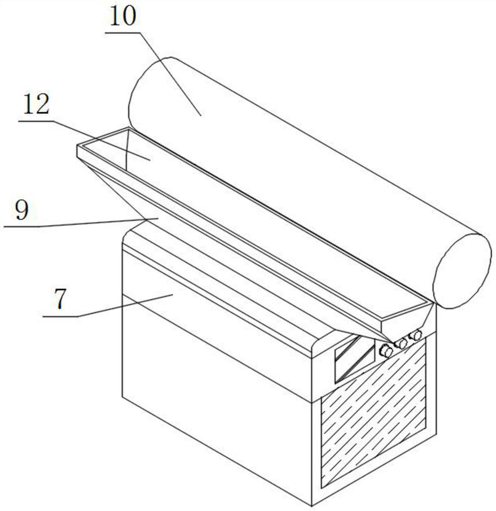
[0053] Such as figure 1 , Figure 7 with Figure 8 As shown, the bottom wall of the U-shaped board 4 is provided with a partition plate 19, and the top of the partition board 19 extends out of the inside of the U-shaped board 4, and the outer wall of one side of the partition board 19 is provided with a through groove 20. One side outer wall of the partition 19 is provided with two sets of moving slots 21 arranged up and down, and the two sets of moving slots 21 are respectively located above and below the through slot 20 .

[0054] The inner wall of the through groove 20 is equipped with two sets of moving blocks 22 arranged front and back, and the outer walls of both sides of the moving block 22 are equipped with rectangular blocks 23, and one of the outer walls of one set of long blocks 23 is installed with two sets of locking blocks arranged up and down. Nails 24, and one end of two groups of locking nails 24 penetrates the interior of two groups of moving grooves 21 and...


PUM


Abstract

The invention discloses textile operation equipment with a thread layer carding structure. The equipment comprises a bottom plate, a front plate, a rear plate, U-shaped inserting plates, traction rollers and a fixing plate; the front plate and the rear plate are installed on the front face and the back face of the bottom plate respectively; the top of the bottom plate is provided with the two sets of U-shaped inserting plates arranged side by side; the front face of the rear plate is provided with the two sets of traction rollers arranged side by side; the fixing plate is installed on the back face of the front plate; and dust suction machines are installed at the bottom of the fixing plate and the top of the bottom plate correspondingly. Miscellaneous wool in a brush rod can be removed through a tooth groove plate, and then the miscellaneous wool is sucked through the dust suction machines; disassembly convenience is achieved among a connecting cylinder, the brush rod and a threaded sleeve; the distance between two sets of moving blocks and the distance between two sets of annular plates arranged in the front-back direction in the equipment are adjustable, so that the equipment has the adjusting and deviation preventing functions on textiles; and when the textiles are conveyed, water can be sprayed to prevent floating of the miscellaneous wool.

Description

technical field [0001] The invention relates to the technical field of textiles, in particular to a textile operation device with a wire layer carding structure. Background technique [0002] With the continuous development of the textile industry, the textile technology has changed from traditional hand spinning and weaving to machine manufacturing. When the machine processes textiles, it is necessary to use the thread layer carding structure to comb the surface of the textile to clean its surface. The miscellaneous wool and other sundries, and then improve the quality of this textile. [0003] The defective that existing line layer carding structure exists is: [0004] 1. Patent document CN212895140U discloses a textile thread layer carding device for textile machines, "comprising a carding machine, the bottom of the carding machine is provided with a base, and the inner side wall of the base is provided with a first chute, the first The inner side of the chute is provid...

Claims


Application Information

Patent Timeline
Patent Type & Authority Applications(China)
IPC IPC(8): D06C11/00D06G1/00D06B1/02B08B1/02B08B15/04
CPCD06C11/00D06G1/00D06B1/02B08B1/02B08B15/04
Inventor 江斌刘立新杨惠祥
Owner 南通中邦丝织有限公司
Why Eureka
Try Eureka