High-precision plate rolling machine based on machine vision

A machine vision, high-precision technology, used in metal processing equipment, metal processing, manufacturing tools, etc., can solve the problems of inconvenient monitoring of curled sheets and waste of staff time.

Pending Publication Date: 2022-07-29
南通威锋重工机械有限公司
View PDF9 Cites 0 Cited by
  • Summary
  • Abstract
  • Description
  • Claims
  • Application Information

AI Technical Summary

Problems solved by technology

"However, in this equipment, it is not convenient to monitor the process of curling the plate. When the plate is curled, the staff needs to observe the degree of curling in real time, which is a waste of staff time.

Method used


Image

  • High-precision plate rolling machine based on machine vision
  • High-precision plate rolling machine based on machine vision
  • High-precision plate rolling machine based on machine vision

Examples


Embodiment 1

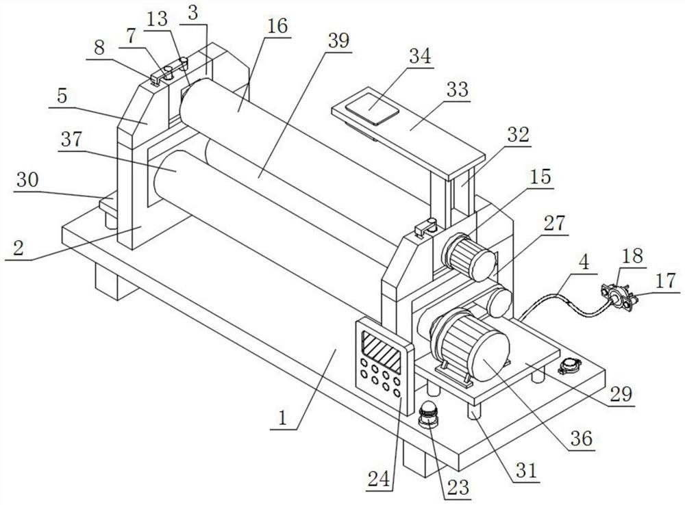
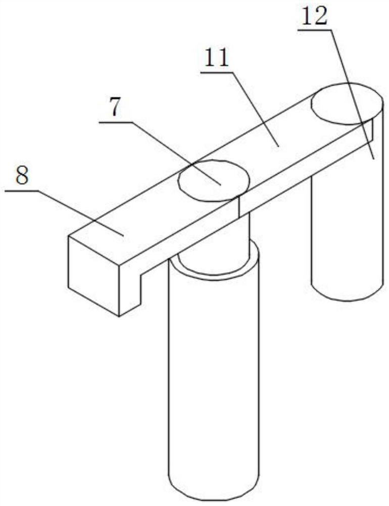
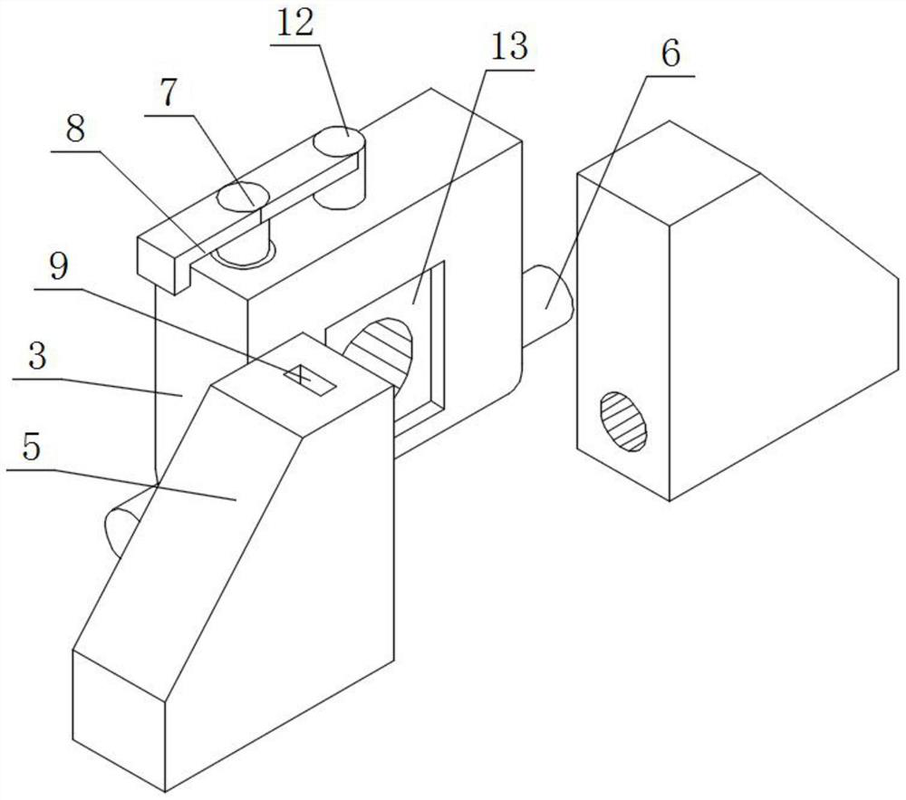
[0042] like figure 1 , figure 2 , image 3 and Figure 4 As shown, a high-precision plate rolling machine based on machine vision includes a base 1, a vertical plate 2, a movable block 3 and a connecting line 4. Two sets of vertical plates 2 arranged side by side are installed on the top of the base 1, and two sets of vertical plates are installed. A movable block 3 is installed on the top of 2;

[0043] Specifically, the base 1 is used to integrate the components installed on its top, and to avoid the bottom of such components directly contacting the ground to be placed, so as to reduce wear and tear. The three groups of rotating rollers installed have enough space for movement, and the two groups of triangular blocks 5 of the movable block 3 are in a non-fixed fit state. For fixed-point rotation, change the placement state of the movable block 3.

[0044] A connecting line 4 is installed on the back of the base 1;

[0045] Specifically, the connecting wire 4 is used a...

Embodiment 2

[0051] like figure 1 and Figure 5 As shown, a socket 17 is installed at the tail end of the connecting wire 4, a protection ring 18 is installed on the outer surface of the socket 17, an assembly plate 19 is installed on the outer walls of both sides of the protection ring 18, and the front surfaces of the two groups of assembly plates 19 are installed. Both are provided with threaded grooves 20, the inner walls of the two sets of threaded grooves 20 are equipped with collars 21, the inner walls of the two sets of collars 21 are equipped with miniature electric extension rods 22, and the top of the base 1 is equipped with a voice prompt 23 and a controller 24, and the voice prompter 23 and the controller 24 are electrically connected, a vibration sensor is installed on the top of the base 1, and the voice prompter 23 of the vibration sensor is electrically connected.

[0052] Specifically, after the socket 17 is connected to the power socket, the device can be powered on to ...

Embodiment 3

[0054] like figure 1 , Image 6 and Figure 8 As shown, one side outer wall of the two sets of vertical plates 2 is provided with a notch 25, the front wall and the rear wall of the notch 25 are provided with a fitting groove 26, and the inner wall of the two sets of notches 25 is installed with a comprehensive block 27, Long strips 28 are mounted on the front and back of the integrated block 27 , and the outer walls of the long strips 28 are in contact with the inner walls of the fitting grooves 26 .

[0055] Specifically, the height of the slot 25 is greater than the height of the integrated block 27, and the integrated block 27 can move up and down inside the slot 25 under the driving of external force to adjust the corresponding height position, and the long strip 28 can be non-fixedly attached to the The interior of the fitting groove 26 increases the connection between the integrated block 27 and the riser 2 .

[0056] A square plate 29 is installed on one outer wall ...


PUM


Abstract

The high-precision plate rolling machine based on machine vision comprises a base, vertical plates, movable blocks and a connecting line, the top of the base is provided with two sets of vertical plates arranged side by side, and the tops of the two sets of vertical plates are both provided with the movable blocks; a connecting wire is mounted on the back surface of the base; the tops of the two vertical plates are each provided with two triangular blocks arranged in a front-back mirror image mode, the front faces and the back faces of the two movable blocks are each provided with a cylinder, the tops of the two movable blocks are each provided with an electric push rod, and the front faces of the two electric push rods are each provided with a folded plate. A curled and formed plate is convenient to take out and not prone to deformation, meanwhile, the distance between the upper rotating roller and the lower rotating roller can be conveniently changed according to the thickness of the plate, visual monitoring and sound monitoring are started when equipment runs, and meanwhile monitored content is transmitted to an external control terminal to be judged and fed back; and the equipment is not used after the set time is exceeded, and has the function of automatically pulling off the power supply after reminding.

Description

technical field [0001] The invention relates to the technical field of plate rolling machines, in particular to a high-precision plate rolling machine based on machine vision. Background technique [0002] The plate rolling machine is a kind of processing equipment that rolls the metal sheet into the required circular, arc or conical shape. It uses the principle of three points to form a circle. It is widely used in various metal processing and equipment production, and has the function of rolling metal sheets into O-shaped, U-shaped, multi-section R-shaped and other different shapes. [0003] The defects of the existing plate rolling machine are: [0004] 1. Patent document CN111872175A discloses a thin-walled plate rolling machine with adjustable roller diameter, "including a plate rolling machine body, the plate rolling machine body includes an end shaft, and the inner wall of the end shaft is provided with a diameter adjustable mechanism, and the diameter can be adjuste...

Claims


Application Information

Patent Timeline
Patent Type & Authority Applications(China)
IPC IPC(8): B21D5/00B21D5/14B21C51/00
CPCB21D5/006B21D5/004B21D5/14B21C51/00
Inventor 宋志锋
Owner 南通威锋重工机械有限公司
Why Eureka
Try Eureka