
Gas flow process detection device and method, air compressor unit and detection method

An air compressor unit and process detection technology, applied in the detection field, to achieve the effect of comprehensive evaluation

Active Publication Date: 2022-01-07
常州萨柏美格医用气体设备有限公司
View PDF22 Cites 1 Cited by
  • Summary
  • Abstract
  • Description
  • Claims
  • Application Information

AI Technical Summary

Problems solved by technology

In the current compressor unit, sensors with a single detection target such as gas pressure, flow rate and temperature are installed at the local circulation position, and comprehensive evaluation results are obtained through the collection and analysis of various sensor data, but none of them is more intuitive. comprehensive detection device

Method used


Image

  • Gas flow process detection device and method, air compressor unit and detection method
  • Gas flow process detection device and method, air compressor unit and detection method
  • Gas flow process detection device and method, air compressor unit and detection method

Examples


Embodiment 1

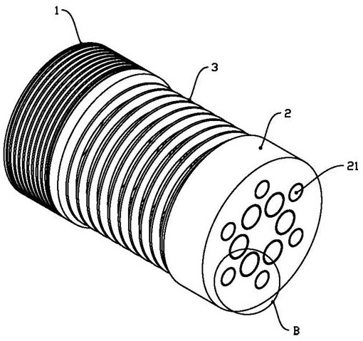
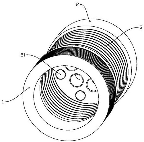
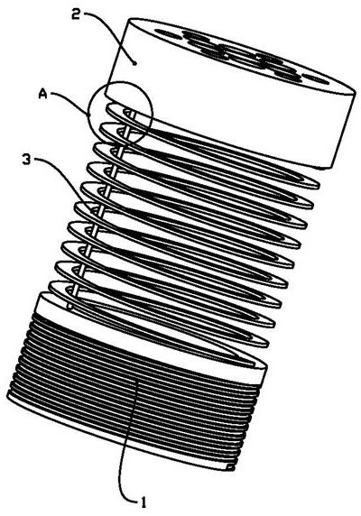
[0049] Such as Figure 1~6As shown, the gas flow process detection device includes: a mounting base 1, which is fixedly connected to the inner wall of the pipeline, and a through passage 11 for gas circulation is provided in the middle; The inner wall of the road is bonded, and the bonding position is sealed. The induction structure 2 is provided with a number of flow passages 21 for the gas to flow to the through passage 11; the buffer structure 3 is arranged between the mounting base 1 and the induction structure 2. For the induction structure 2 Elastic cushioning is performed relative to the movement of the mounting base 1; the probe 4 is fixedly connected to the mounting base 1 or the sensing structure 2, and detects the distance of the sensing structure 2 relative to the mounting base 1; the sensing structure 2 includes an elastic body 22 and a guide The trachea 23 and the elastic body 22 are attached to the inner wall of the pipeline, and have a closed cavity inside, fil...

Embodiment 2

[0058] The gas flow process detection method adopts the gas flow process detection device in Embodiment 1, takes time as the abscissa, and the length value of the probe 4 as the ordinate to establish a coordinate system, determines points on the coordinate system through the collected data, and connects Each point and through the trend reflect the flow process of gas.

[0059] In the present invention, the type of data collected is relatively simple, compared with the way of comprehensively analyzing and comparing multiple sets of data in the prior art to obtain conclusions, it is more intuitive. The fluctuation of the position and the change of the expansion state due to fluctuations convert the imperceptible gas flow state in the pipeline into a visually recognizable trend line form, thus making the detection conclusion more intuitive.

[0060] Such as Figure 7 As shown, the width range between the two sets of parallel dotted lines at the top and bottom of the figure is th...

Embodiment 3

[0070] Such as Figure 9~11 As shown, the air compressor unit includes the gas flow process detection device in Embodiment 1, and the sequentially connected compressor unit 7, air storage tank 8 and drying unit 9; the compressor unit 7 includes several groups of compression units 71, at least one compressor Unit 71 is used as a spare unit, and the air intake position and the air outlet position of compression unit 71 are respectively provided with a first-stage filter structure 72 and a second-stage filter structure 73; the drying unit 9 includes several groups of drying units 91, at least one drying unit 91 is used as a backup unit, and the air intake position and the air outlet position of the drying unit 91 are respectively provided with a third-stage filter structure 92 and a fourth-stage filter structure 93 .

[0071] Wherein, the pipelines at the outlets of the first-stage filter structure 72 , the second-stage filter structure 73 , the third-stage filter structure 92 an...


PUM


Abstract

The invention relates to the technical field of detection, in particular to a gas flow process detection device. The gas flow process detection device comprises a mounting seat fixedly connected with the inner wall of a pipeline, a sensing structure which is sealed with the inner wall of the pipeline and is provided with a plurality of flow passing channels, a buffering structure arranged between the mounting seat and the sensing structure, and a probe used for detecting the distance between the sensing structure and the mounting seat. The invention provides a detection device and method which can relatively directly reflect the gas flow process, and various abnormal possibilities that influence gas flow can be reflected through a single parameter through collection of the state change of the device and the length data of the probe. An air compressor unit is further included, the gas flow process detection device is adopted, and the air compressor unit comprises a compressor unit, an air storage tank and a drying unit which are connected in sequence; and the trend lines of the gas flow process in different positions can be obtained through the gas flow process detection devices arranged in different positions and the corresponding detection method, and comprehensive evaluation of the gas flow process is realized.

Description

technical field [0001] The invention relates to the technical field of detection, in particular to a gas flow process detection device and method, an air compressor unit and a detection method. Background technique [0002] As a kind of medical gas, medical compressed air is widely used in hospitals, and it is distributed in every corner of the hospital medical system. The core equipment of the compressed air system consists of compressor unit, air storage tank, drying unit, filter device, dew point detection, carbon monoxide detection and control cabinet, etc. [0003] For medical compressed air, the most important concern is the quality of the compressed air and the continuity of the air supply of the air source. At present, the compressed air quality indicators mainly include the oil content, water content, particle content, etc. of the compressed air, which can be achieved through effective filtration and drying processes; the continuity of the air supply is easy to be ...

Claims


Application Information

Patent Timeline
IPC IPC(8): F04B51/00F04B41/02F04B41/06F04B39/16G01L11/00G01M9/06
CPCF04B51/00F04B41/02F04B41/06F04B39/16G01L11/00G01M9/065
Inventor 杨岳兴马逸天谢彬蒋文滔刘承洪
Owner 常州萨柏美格医用气体设备有限公司
Learn More