Reciprocating type stirring device

A stirring device, reciprocating technology, applied in the directions of transportation and packaging, dissolving, mixer, etc., can solve the problems of low stirring efficiency, insufficient stirring, and layering of materials up and down, so as to improve the stirring effect and improve the stirring efficiency. , reduce the effect of power source devices

Pending Publication Date: 2022-01-11
浙江祥生建设工程有限公司
View PDF0 Cites 0 Cited by
  • Summary
  • Abstract
  • Description
  • Claims
  • Application Information

AI Technical Summary

Problems solved by technology

[0004] Aiming at the technical problems that the existing stirring device tends to be layered up and down, the stirring is not uniform enough, and the stirring efficiency is not high, the present invention provides a reciprocating stirring device, which is provided with a counter-rotating stirring shaft and a casing to realize Double stirring, and the blades on the stirring shaft and the shell are set in a continuous spiral shape, the material at the stirring shaft moves downward with the blade rotation of the stirring shaft, and the material at the shell moves upward with the blade rotation of the shell, forming a reciprocating Stirring mode, the stirring shaft and the casing are connected with a planetary gear system and a driving mechanism to realize the reverse rotation of the stirring shaft and the casing

Method used


Image

  • Reciprocating type stirring device
  • Reciprocating type stirring device
  • Reciprocating type stirring device

Examples


Embodiment 1

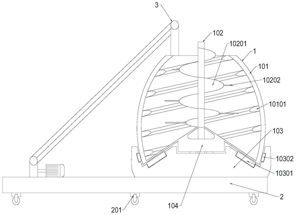
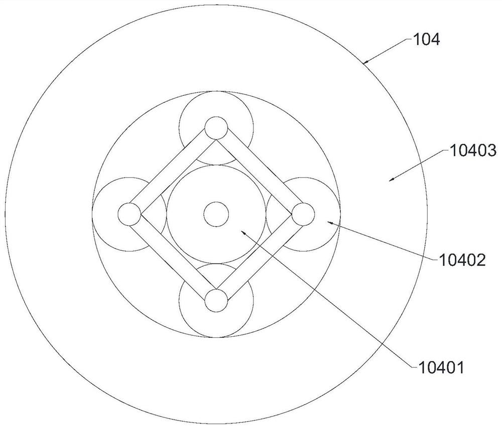
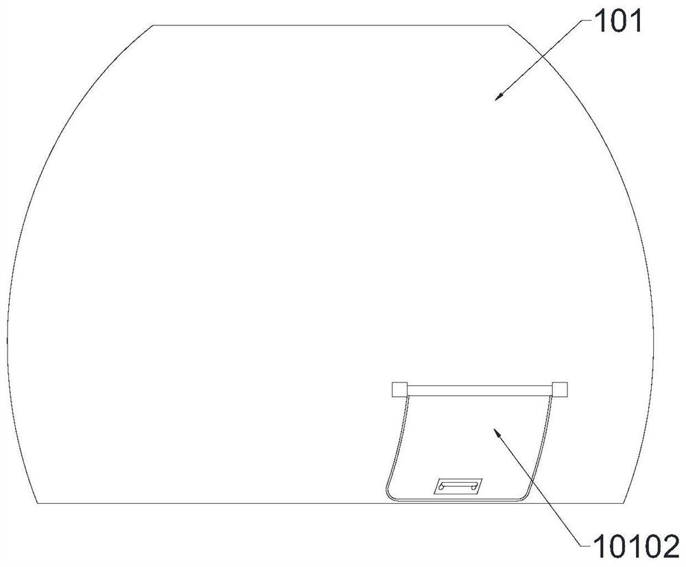
[0027] combined with Figure 1-3 , a reciprocating stirring device, including a stirring module 1, a moving seat 2 and a feeding module 3, the stirring module 1 and the feeding module 3 are fixed on the moving seat 2, and the stirring module 1 includes a shell 101 , a stirring shaft 102, a base 103 and a planetary gear system 104, the top of the housing 101 is provided with a feed port connected to the feeding module 3, the stirring shaft 102 is located on the central axis of the housing 101, the The stirring shaft 102 is rotatably connected to the casing 101 and the planetary gear system 104, the rotation direction of the casing 101 and the stirring shaft 102 is opposite, and the inner surface of the casing 101 is provided with a helical first blade 10101 The peripheral side of the stirring shaft 102 is provided with a helical second blade 10201, the base 103 is provided with a driving mechanism connected with the stirring shaft 102, and the planetary gear system 104 includes...

Embodiment 2

[0040] A kind of reciprocating stirring device of this embodiment, compared with the technical scheme of embodiment 1, can be improved as follows: feed module 3 adopts pipeline transportation, considers that some materials themselves are not easy to be transported by conveyor belt, such as water, liquid For materials, etc., the pipeline is connected with a pump body, and the materials that are not easy to be transported by the conveyor belt can be added to the stirring device.


PUM


Abstract

The invention discloses a reciprocating type stirring device, and belongs to the technical field of building machinery. The reciprocating type stirring device comprises a stirring module, a moving seat and a feeding module; the stirring module comprises a shell, a stirring shaft, a base and a planetary gear system; the stirring shaft is rotatably connected to the shell and the planetary gear system; the rotating directions of the shell and the stirring shaft are opposite; a spiral first blade is arranged on the inner surface of the shell; a spiral second blade is arranged on the peripheral side of the stirring shaft. The stirring shaft and the shell which rotate reversely are arranged, so that double stirring is realized, and the stirring efficiency is improved; a reciprocating stirring mode is formed, the situation that materials are layered in a vertical direction is avoided, the materials at the stirring shaft and the materials at the shell move relatively, the materials generate a grinding process, so that the stirring efficiency and the stirring effect are further improved; and the stirring shaft and the shell are connected with the planetary gear system and a driving mechanism, power source devices are reduced, energy is saved, and meanwhile maintenance is convenient.

Description

technical field [0001] The invention relates to the technical field of construction machinery, in particular to a reciprocating stirring device. Background technique [0002] The mixer is a common equipment on the construction site. It mainly plays the role of mixing cement or various kinds of paint. The traditional mixer is generally cylindrical, with a rotating stirring rod inside, and the material is added manually. After the mixing is completed, the material is manually taken out. . And when stirring the materials, only the stirring rod rotates, and the stirring efficiency of the materials is not high. Contents of the invention [0003] 1. The technical problem to be solved by the invention [0004] Aiming at the technical problems that the existing stirring device tends to be layered up and down, the stirring is not uniform enough, and the stirring efficiency is not high, the present invention provides a reciprocating stirring device, which is provided with a count...

Claims


Application Information

Patent Timeline
Patent Type & Authority Applications(China)
IPC IPC(8): B01F29/83B01F29/85
Inventor 蔡越杨向东王露露吴春良孙笠滔
Owner 浙江祥生建设工程有限公司
Why Eureka
Try Eureka