Industrial piping cold-drawing device and cold-drawing process

An industrial and clamping device technology, which is applied in the field of industrial piping cold drawing device, can solve the problems affecting the lubrication and cold drawing effect and the generation of impurities, so as to improve the lubrication effect and cleaning effect, reduce the impact and prolong the service life of the equipment

Inactive Publication Date: 2020-12-29
浙江德传管业有限公司
View PDF1 Cites 0 Cited by
  • Summary
  • Abstract
  • Description
  • Claims
  • Application Information

AI Technical Summary

Problems solved by technology

[0004] However, when the equipment is used, the steel pipe needs to be cleaned separately, and then lubricated and cold-drawn. The cleaned steel pipe is likely to generate impurities again during the storage and transfer process, which affects the lubrication and cold-drawing effect.

Method used


Image

  • Industrial piping cold-drawing device and cold-drawing process
  • Industrial piping cold-drawing device and cold-drawing process
  • Industrial piping cold-drawing device and cold-drawing process

Examples


Embodiment 1

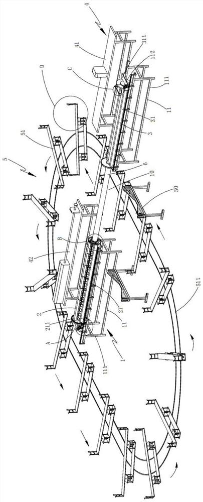
[0058] like figure 1 As shown, an industrial pipe cold drawing device includes:

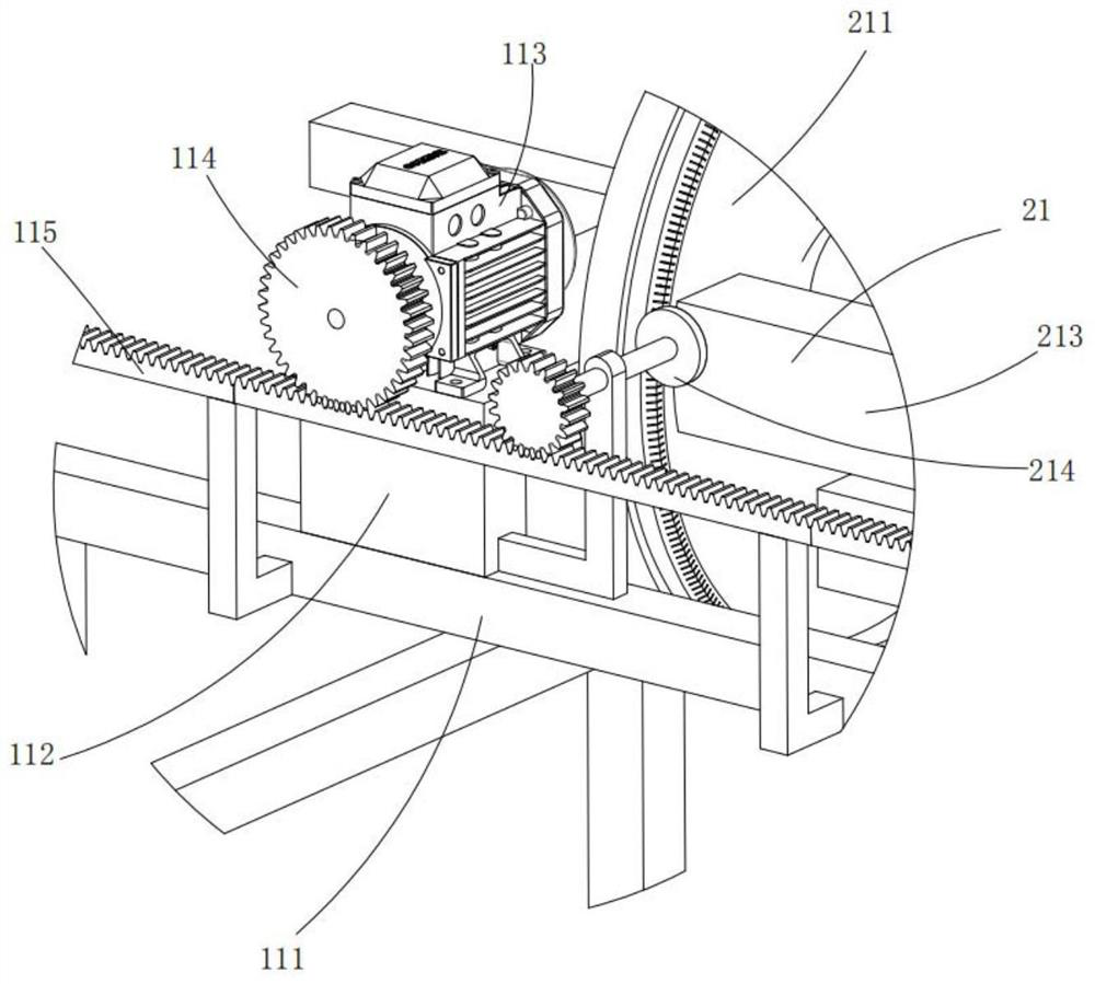
[0059] Clamping device 1, said clamping device 1 includes two moving components 11 arranged on both sides of the clamping station 10 and a positioning component 12 fixed on any one of said moving components 11;

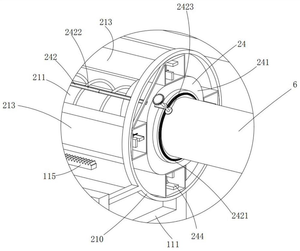
[0060] The lubricating device 2, the lubricating device 2 includes a rotating component 21 that is rotatably mounted on the other moving component 11 relative to the positioning component 12 and is facing the positioning component 12, and is installed at the center of the end of the moving component 11 The internal lubricating assembly 22 at the position, the external lubricating assembly 23 installed on the end of the rotating assembly 21 and arranged around the internal lubricating assembly 22, and the external lubricating assembly 23 which is slidably arranged on the rotating assembly 21 and drives the internal lubricating assembly 22 and the internal lubricating assembly 22. The out...

Embodiment 2

[0086] like Figure 19 As shown, the industrial pipe cold drawing process of the second embodiment of the present invention is described with reference to the first embodiment, which is characterized in that it includes the following steps:

[0087] Step 1: clamping the steel pipe, the feeding assembly 51 sends the steel pipe at the storage area 50 to the clamping station 10, the moving assembly 11 moves forward so that the limit assembly 24 cooperates with the positioning assembly 12 to clamp and fix the steel pipe;

[0088] Step 2: The cleaning assembly moves. After step 1, the moving assembly 11 on the other side sends the cleaning assembly 32 to the end of the steel pipe near the inner lubrication assembly 22 and the outer lubrication assembly 23, and the driving assembly 33 drives the cleaning assembly 32 and the outer lubrication assembly 23. steel pipe contact;

[0089] Step 3: Lubricate the steel pipe. After step 2, the moving assembly 11 cooperates with the conical t...


PUM


Abstract

The invention discloses an industrial piping cold-drawing device. The industrial piping cold-drawing device comprises a clamping device, a lubricating device, a cleaning device, a cold-drawing deviceand a feeding device, wherein the clamping device comprises a moving assembly and a positioning assembly, the lubricating device comprises a rotating assembly, an inner lubricating assembly, an outerlubricating assembly and a limiting assembly, the inner lubricating assembly and the outer lubricating assembly comprise spraying mechanisms and rolling brush mechanisms, the cleaning device comprisesan installing assembly, a clearing assembly and a driving assembly, and the feeding assembly comprises a feeding assembly. According to the industrial piping cold-drawing device and the cold-drawingprocess, a steel pipe is fixed through the clamping device, the clearing assembly polishes and clears the inner wall and the outer wall of the steel pipe firstly, meanwhile, the inner lubricating assembly and the outer lubricating assembly lubricate the polished inner wall and the polished outer wall of the steel pipe at the same time, steel pipe polishing and steel pipe lubricating are conductedat the same time, and the production efficiency is greatly improved and the equipment damage is reduced.

Description

technical field [0001] The invention relates to the field of industrial piping production equipment, in particular to an industrial piping cold drawing device. Background technique [0002] Cold drawing is a processing technology of materials. For metal materials, cold drawing refers to drawing under the condition that the material is at room temperature in order to achieve a certain shape and certain mechanical properties. Forming has the advantages of high dimensional accuracy and good surface finish. Therefore, industrial piping is mostly made by cold drawing process, and the steel pipe needs to be lubricated before cold drawing. [0003] The invention patent with the Chinese patent application number CN201810211011.2 discloses a cold drawing die with saponification function, which is characterized in that it includes a core rod, an outer mold, an inner mold, an outer mold sealing ring, an inner mold sealing ring and a core rod seal ring; the inner mold is fixed on the c...

Claims


Application Information

Patent Timeline
Patent Type & Authority Applications(China)
IPC IPC(8): B21C9/00B21C43/02B21C1/22B21C1/32
CPCB21C1/22B21C1/32B21C9/00B21C43/02
Inventor 王皓哲毛珍凤容松如
Owner 浙江德传管业有限公司
Why Eureka
Try Eureka