Supercharge Your Innovation With Domain-Expert AI Agents!

Insert tool

A plug-in, tool technology, applied in the direction of manufacturing tools, impact tools, light impact tools, etc., can solve the problems of drilling tool staining, high cost of drilling tools, etc.

Pending Publication Date: 2022-01-11
ROBERT BOSCH GMBH
View PDF0 Cites 0 Cited by
  • Summary
  • Abstract
  • Description
  • Claims
  • Application Information

AI Technical Summary

Problems solved by technology

Additionally, to manufacture the conveyor auger, drill bits must be attached and / or ground and the drilling tool may also be stained
Therefore, the manufacturing process of drilling tools is very costly

Method used


Image

  • Insert tool
  • Insert tool
  • Insert tool

Examples


Embodiment Construction

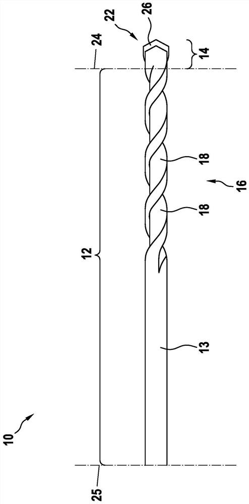
[0028] exist figure 1 A side view of the base module 10 is shown in . The base module 10 is provided for a plug-in tool 100 configured, for example, as a rock drill 102 (see Figure 5 ). The base module 10 has a first section 12 and a second section 14 .

[0029] The first section 12 includes a base body 13 and is designed, for example, in one piece. The first section 12 consists, for example, of steel. The first section 12 has a conveying screw 16 which is, for example, double-ended. Accordingly, the conveying screw 16 has two grooves 18 which extend helically around the longitudinal axis 20 of the base module 10 . The conveying screw 16 extends, for example, along approximately 50% of the length of the base module 10 and extends from the middle up to the start of the second section 14. The region of the base body 13 facing away from the second section 14 has a cylindrical peripheral surface without grooves.

[0030] The second section 14 includes a cutting body 22 , w...


PUM


Abstract

The invention relates to an insert tool, in particular a drilling tool, having a base module, wherein the base module has a first portion, which in particular includes a conveying helix, and a second portion, which includes cutting bodies with preferably at least two cutting faces. The second portion is connected to a first end of the first portion in an integrally bonded manner. The base module is connected, at a second end, to an, in particular hardened, insertion end in an integrally bonded manner by way of in particular a friction welding method.

Description

technical field [0001] The invention relates to an insertion tool and a method of manufacturing an insertion tool. Background technique [0002] The manufacturing process of drilling tools is complex. Starting from the blank, the shank is first adapted to the provided tool holder of the hand power tool. Furthermore, to manufacture the conveying auger, drill bits must be attached and / or ground and the drilling tools may also be stained. Therefore, the manufacturing process of the drilling tool is very costly. Contents of the invention [0003] The invention relates to an insertion tool, in particular a drilling tool, having a base module, wherein the base module has a first section and a second section, the first section in particular comprising a conveying screw, the The second section comprises a cutting body having preferably at least two cutting surfaces, wherein the second section is connected to the first end of the first section in a materially bonded manner. The...

Claims


Application Information

Patent Timeline
Patent Type & Authority Applications(China)
IPC IPC(8): B23B51/02B25D16/00B25D17/02
CPCB23B51/02B25D17/02B25D16/00B23B2226/75B23B2260/104B23B2270/36B23K2101/20B23B2251/20B23B2240/16B23B2228/24
Inventor M·安吉莱里
Owner ROBERT BOSCH GMBH
Features
  • R&D
  • Intellectual Property
  • Life Sciences
  • Materials
  • Tech Scout
  • Unparalleled Data Quality
  • Higher Quality Content
  • 60% Fewer Hallucinations
Learn More