Supercharge Your Innovation With Domain-Expert AI Agents!

Laser cladding device with adjustable wire outlet direction

A laser cladding and wire technology, applied in metal material coating process, coating and other directions, can solve the problems of high skill requirements, damage, risk of increasing maintenance costs, etc., to ensure accuracy, reduce nozzle wear, improve Sliding smoothness effect

Pending Publication Date: 2022-01-11
SUZHOU INST OF INDAL TECH
View PDF0 Cites 0 Cited by
  • Summary
  • Abstract
  • Description
  • Claims
  • Application Information

AI Technical Summary

Problems solved by technology

The existing adjustment method is to manually adjust the optical components inside the laser cladding device. Since the optical components are precision and expensive components, they are easily damaged after repeated adjustment operations, which increases the risk of paying expensive maintenance costs.
Moreover, the operation of optical devices often requires very small and precise operations, which requires high skills for technicians

Method used


Image

  • Laser cladding device with adjustable wire outlet direction
  • Laser cladding device with adjustable wire outlet direction
  • Laser cladding device with adjustable wire outlet direction

Examples


Embodiment 1

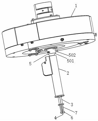
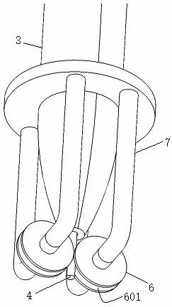
[0027] see figure 1 , figure 2 and Figure 7 As shown, a laser cladding device with adjustable wire outlet direction includes a three-beam laser cladding nozzle 1, the three-beam laser cladding nozzle 1 is connected to a wire nozzle 3 through a wire guide post 2, and the wire One side of the material guide post 2 is provided with a wire entry hole 201 and a wire passage 202 is opened in the middle, and the wire 4 used for cladding enters the wire passage 202 from the wire entry hole 201 and passes through the wire passage 202. The incident laser beam passes through the three-beam laser cladding nozzle 1 to generate three beams projected below the wire nozzle 3 and envelops the wire 4 emitted from the wire nozzle 3. The wire guide post 2 is movably connected with the three-beam laser cladding nozzle 1 .

[0028] Further, the wire guide post 2 is movably connected with the three-beam laser cladding nozzle 1 through a universal ball hinge mechanism 5 .

[0029] Further, the ...

Embodiment 2

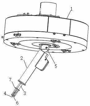
[0034] see Figure 4 , Figure 5 and Figure 7As shown, a laser cladding device with adjustable wire outlet direction includes a three-beam laser cladding nozzle 1, the three-beam laser cladding nozzle 1 is connected to a wire nozzle 3 through a wire guide post 2, and the wire One side of the material guide post 2 is provided with a wire entry hole 201 and a wire passage 202 is opened in the middle, and the wire 4 used for cladding enters the wire passage 202 from the wire entry hole 201 and passes through the wire passage 202. The incident laser beam passes through the three-beam laser cladding nozzle 1 to generate three beams projected below the wire nozzle 3 and envelops the wire 4 emitted from the wire nozzle 3. The wire guide post 2 is movably connected with the three-beam laser cladding nozzle 1 .

[0035] Further, the wire guide post 2 is movably connected with the three-beam laser cladding nozzle 1 through a universal ball hinge mechanism 5 .

[0036] Further, the ...


PUM


Abstract

The invention discloses a laser cladding device with an adjustable wire outlet direction. The laser cladding device comprises a three-beam laser cladding spray head, wherein the three-beam laser cladding spray head is connected with a wire nozzle through a wire guide column; a wire inlet hole is formed in one side of the wire guide column, and a wire passage is formed in the middle of the wire guide column; a wire for cladding enters the wire passage from the wire inlet hole and is ejected through the wire nozzle; an incident laser beam generates three beams through the three-beam laser cladding spray head, and the three beams are projected below the wire nozzle and envelope the wire ejected from the wire nozzle; and the wire guide column is movably connected with the three-beam laser cladding spray head. The laser cladding device disclosed by the invention is adopted with another idea, and the position of the wire ejected from the wire nozzle is adjusted, so that the position relationship between a laser beam spot and the wire is adjusted, and a good envelope relationship between the spot and the wire can be obtained without adjusting a precise optical assembly.

Description

technical field [0001] The invention belongs to the technical field of laser cladding, and in particular relates to a laser cladding device. Background technique [0002] Laser cladding (also known as laser cladding or laser cladding) is a new surface modification technology. It forms a metallurgically bonded cladding layer on the surface of the base by adding cladding materials on the surface of the substrate and using a high-energy-density laser beam to fuse it together with the thin layer on the surface of the substrate. [0003] Laser cladding features: the cladding layer has low dilution but strong binding force, and is metallurgically bonded to the substrate, which can significantly improve the wear resistance, corrosion resistance, heat resistance, oxidation resistance or electrical properties of the substrate material surface, so as to achieve surface modification or The purpose of repair is to meet the specific performance requirements of the material surface and s...

Claims


Application Information

Patent Timeline
Patent Type & Authority Applications(China)
IPC IPC(8): C23C26/02
CPCC23C26/02
Inventor 石皋莲刘凡吉绍山耿哲黄厚涛丁倩倩
Owner SUZHOU INST OF INDAL TECH
Features
  • R&D
  • Intellectual Property
  • Life Sciences
  • Materials
  • Tech Scout
  • Unparalleled Data Quality
  • Higher Quality Content
  • 60% Fewer Hallucinations
Learn More