
Heat insulation device for outdoor window

A technology of heat insulation device and exterior window, applied in special equipment for doors/windows, solar collectors in specific environments, windows/doors, etc. , affecting indoor lighting and other issues, to achieve good thermal insulation effect, improve service life, improve the effect of cooling effect

Pending Publication Date: 2022-01-11
司马通
View PDF0 Cites 0 Cited by
  • Summary
  • Abstract
  • Description
  • Claims
  • Application Information

AI Technical Summary

Problems solved by technology

The above method has the following defects: 1. The installation process of the sunshade is cumbersome and complicated; 2. The sunshade is installed on the outside of the window, which is easily affected by strong wind or rainstorm and is easily damaged; 3. Installing the sunshade or sticking a film on the surface of the window will block part of the light. Affect indoor lighting

Method used


Image

  • Heat insulation device for outdoor window
  • Heat insulation device for outdoor window
  • Heat insulation device for outdoor window

Examples


Embodiment 1

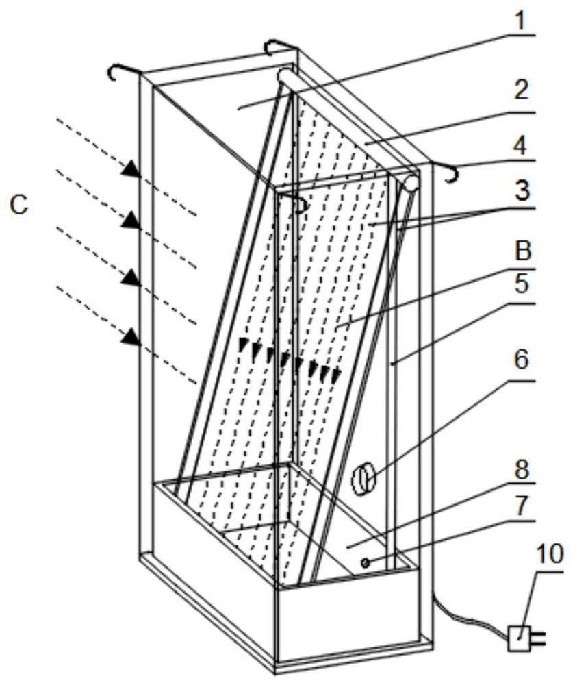
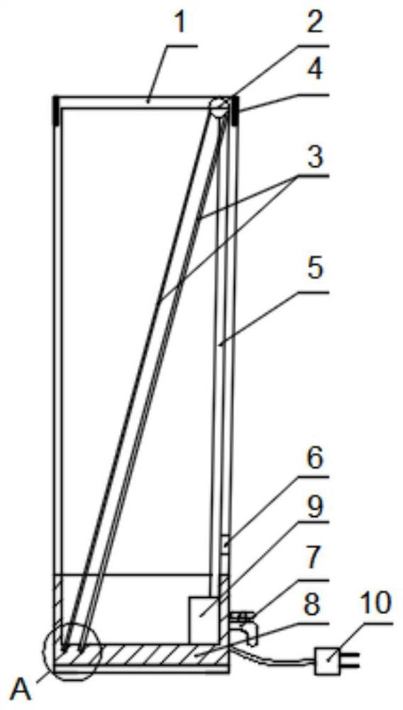
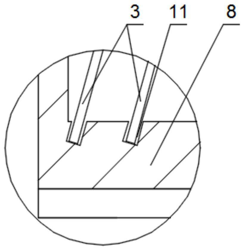
[0039] Such as figure 1 , figure 2 As shown, a heat insulation device for outdoor windows provided by the present invention includes a transparent box 1, at least one transparent deflector 3 and at least one horizontal tube 2, and the top of the box 1 is fixed with The horizontal tube 2, the deflector 3 is installed obliquely in the box 1, and its top is in contact with the horizontal tube 2, the bottom of the box 1 is provided with a water tank 8, and the bottom of the deflector 3 The end is placed in the water tank 8; the bottom of the horizontal pipe 2 is provided with a water outlet; at least one water pump 9 is fixed in the water tank 8, and the water pump 9 and the horizontal pipe 2 are connected by a vertical pipe 5 ; The tank 1 above the water tank 8 is provided with a water inlet 6, and the water inlet 6 is used to connect a water inlet pipe.

[0040] At least one hook 4 is fixedly installed on both sides of the box body 1, attached figure 1 The hooks 4 are instal...

Embodiment 2

[0049] On the basis of the first embodiment, further, the bottom of the box body 1 is provided with a supporting frame 12, and the supporting frame 12 includes four supporting legs. When the window is a bottom-opening type, through the setting of the support frame 12, the purpose of opening the window can be realized without moving the heat insulating device.

Embodiment 3

[0051] On the basis of Embodiment 1, a horizontal tube 2 is added, and the two horizontal tubes 2 are fixed on the top of the box body 1 in parallel, and the bottom of each horizontal tube 2 is respectively fixed with one of the deflectors 3 . Two water pumps 9 are fixedly mounted on both sides of the water tank 8 , and each of the water pumps 9 is connected to one of the horizontal pipes 2 through the vertical pipe 5 .


PUM


Abstract

The invention discloses a heat insulation device for an outdoor window. The heat insulation device comprises a transparent box body, at least one transparent flow guide plate and at least one transverse pipe; the transverse pipes are fixedly mounted at the top of the box body; the flow guide plates are obliquely mounted in the box body, and the top ends of the flow guide plates make contact with the transverse pipes; a water tank is arranged at the bottom of the box body, and the bottom ends of the flow guide plates are arranged in the water tank; water outlets are formed in the bottoms of the transverse pipes; at least one water pump is fixedly mounted in the water tank, and the water pumps and the transverse pipes are connected through vertical pipes; and a water inlet is formed in the position, above the water tank, of the box body. According to the heat insulation device for the outdoor window, the multiple flow guide plates are arranged in the box body, and therefore the box body is divided into multiple closed spaces; flowing water curtains are formed on the flow guide plates and absorb heat of sunlight, the temperature of the closed spaces is gradually decreased from outside to inside, and therefore hot air is effectively prevented from being transmitted into a room; and the heat insulation device effectively prevents heat transmission and is good in heat insulation effect.

Description

technical field [0001] The invention belongs to the technical field of heat insulation, and relates to outdoor windows, in particular to a heat insulation device for outdoor windows. Background technique [0002] There is plenty of sunshine in summer, and the closer to the summer solstice, the longer the sunshine time. Strong sunlight entering the room will cause the indoor temperature to rise sharply. Especially for the apartment types with windows facing west, it is necessary to install heat insulation devices at the outdoor windows to cool down. [0003] The heat insulation methods for outdoor windows in the prior art are mainly to install a sunshade on the outside of the window or stick a film on the window surface. The above method has the following defects: 1. The installation process of the sunshade is cumbersome and complicated; 2. The sunshade is installed on the outside of the window, which is easily affected by strong wind or rainstorm and is easily damaged; 3. In...

Claims


Application Information

Patent Timeline
IPC IPC(8): E06B5/16E06B7/14E06B7/28E06B9/24E06B1/70F24S20/63
CPCE06B5/16E06B7/14E06B9/24E06B7/28E06B1/702F24S20/63Y02E10/40
Inventor 司马通
Owner 司马通
Learn More