Backward centrifugal fan efficiency-increasing wheel disc and backward centrifugal fan

A centrifugal fan and roulette technology, which is applied to machines/engines, mechanical equipment, liquid fuel engines, etc., can solve problems such as the inability to meet the application scenarios of static pressure efficiency, and achieve strong performance, low power consumption, and static pressure efficiency. high effect

Pending Publication Date: 2022-01-11
FANS TECH ELECTRIC CO LTD
View PDF2 Cites 0 Cited by
  • Summary
  • Abstract
  • Description
  • Claims
  • Application Information

AI Technical Summary

Problems solved by technology

The rear disc of the wind rotor in this invention is in the shape of a cone, and the profile line of the meridional channel disc is a spline curve, which cannot meet certain application scenarios with high static pressure efficiency requirements

Method used


Image

  • Backward centrifugal fan efficiency-increasing wheel disc and backward centrifugal fan
  • Backward centrifugal fan efficiency-increasing wheel disc and backward centrifugal fan
  • Backward centrifugal fan efficiency-increasing wheel disc and backward centrifugal fan

Examples


Embodiment 1

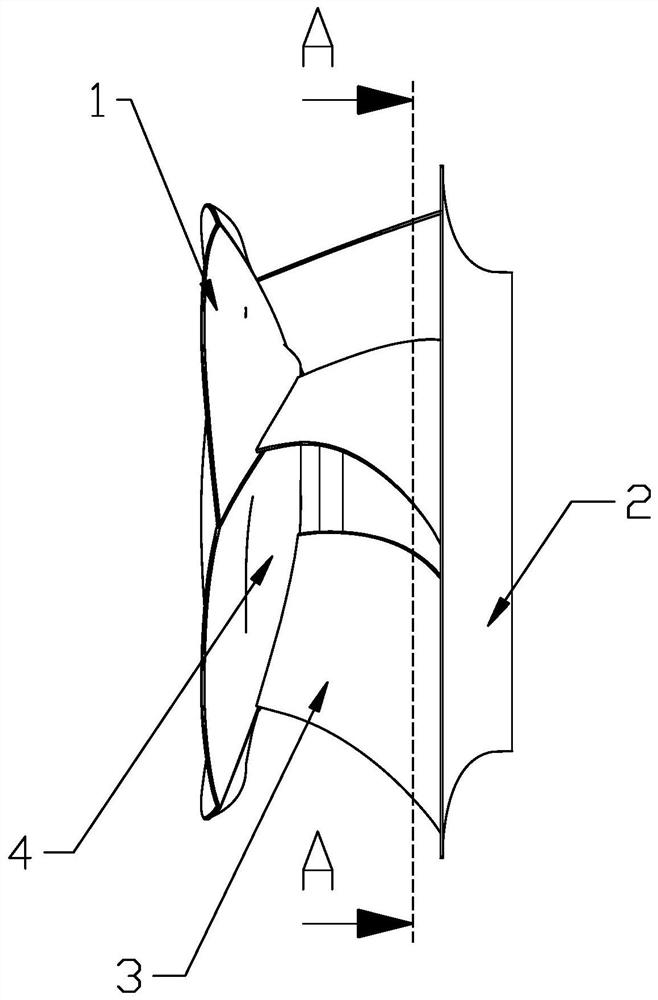
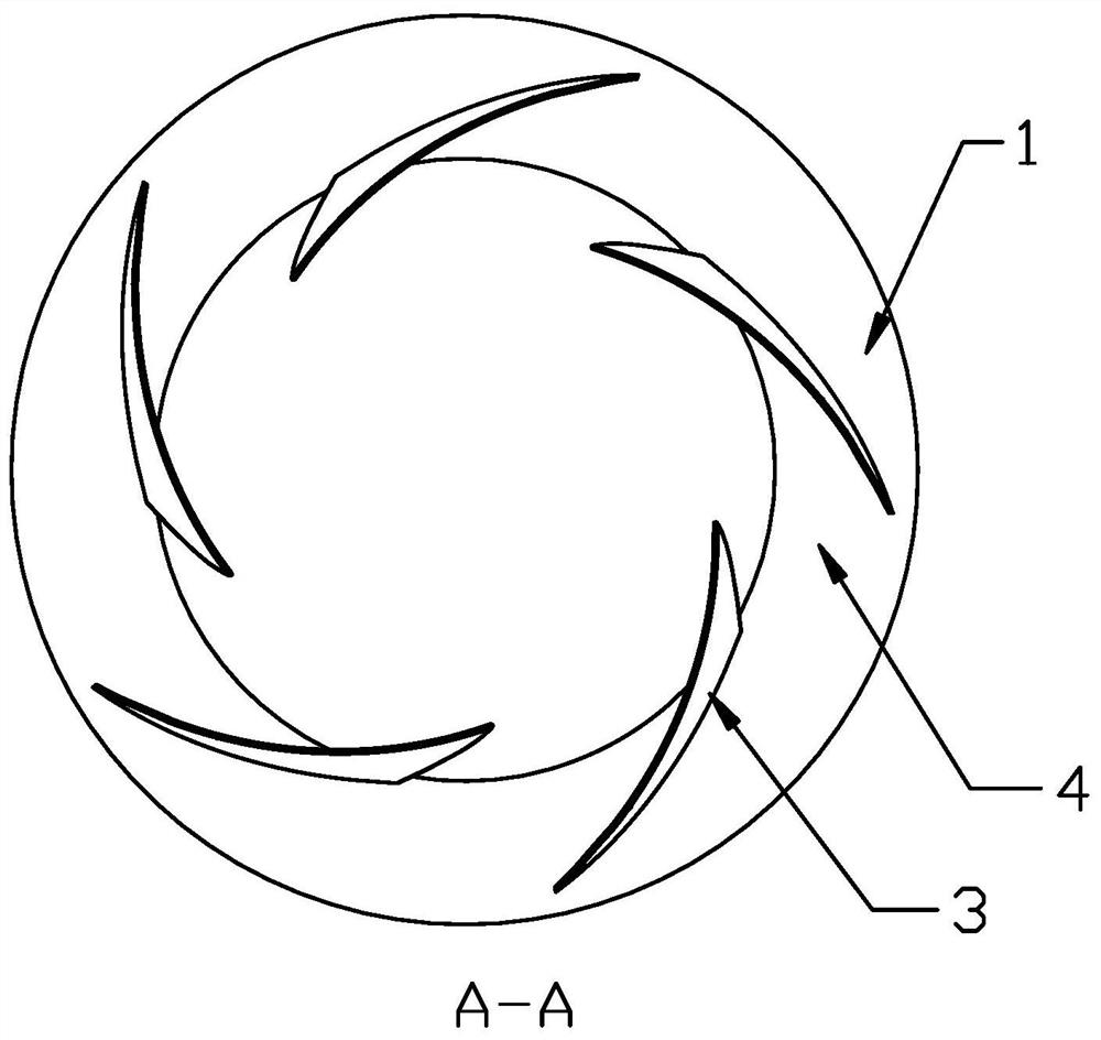
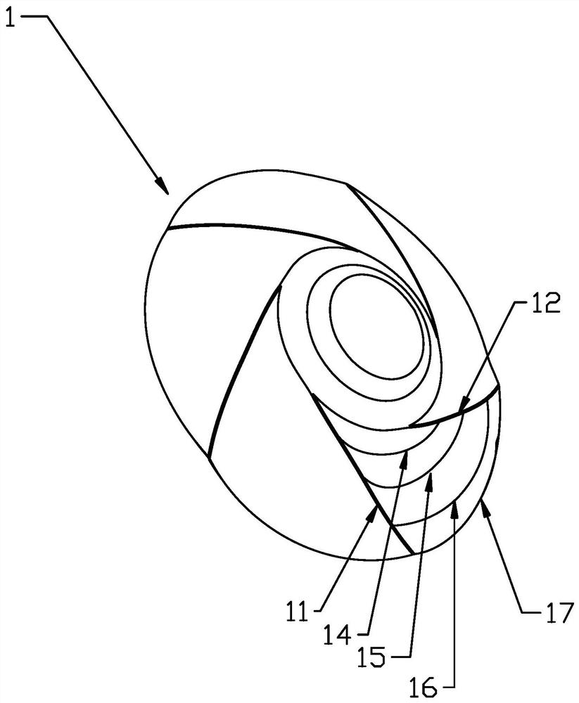
[0034] Such as figure 1 As shown, a backward centrifugal fan efficiency raising wheel 1, the wheel 1 is used to provide installation positions for the blades 3 of the centrifugal fan, and every two adjacent blades 3 are in contact with the surface of the wheel 1 and the wheel cover 2 Meridian flow channels 4 are formed between them, and the roulette 1 includes several meridian surfaces 41, and each meridian surface 41 corresponds to a meridian flow channel 4, that is, several meridian flow channels 4 divide the roulette 1 into several meridian planes 41, such as image 3 As shown, the meridian surface 41 includes a first radial profile 11, a second radial profile 12 and several circumferential profiles, the first radial profile 11 and the second radial profile 12 are any The extension line of the intersection line between two adjacent blades 3 in a meridian channel 4 and the installation position of the wheel disk 1, the first radial profile 11 and the second radial profile 1...

Embodiment 2

[0048] This embodiment only describes the differences from the above-mentioned embodiments. In this embodiment, along the radial direction, the circumferential profiles include four concave circumferential profiles and one convex circumferential profile 16, along the From the starting point to the end point of the first radial profile line 11, the circumferential profile line sequentially includes a first concave circumferential profile line 14, a second concave circumferential profile line 15, an upward convex circumferential profile line 16, The third concave circumferential profile line 17, the fourth concave circumferential profile line, the convex circumferential profile line 16 is set on the second concave circumferential profile line 15, the third concave circumferential profile line 17 , the fourth concave circumferential profile is located on the circumferential edge of the wheel 1 .

Embodiment 3

[0050] This embodiment only describes the differences from the above-mentioned embodiments. In this embodiment, along the radial direction, the circumferential profiles include four concave circumferential profiles and two convex circumferential profiles 16, Along the direction from the starting point to the end point of the first radial profile line 11, the circumferential profile line sequentially includes a first concave circumferential profile line 14, a second concave circumferential profile line 15, a first convex circumferential profile line line 16, the third concave circumferential profile line 17, the second upward convex circumferential profile line 16, the fourth concave circumferential profile line, the fourth concave circumferential profile line is located on the periphery of the wheel disc 1 towards the edge.


PUM


Abstract

The invention discloses a backward centrifugal fan efficiency-increasing wheel disc and a backward centrifugal fan. The wheel disc comprises a plurality of meridian planes, each meridian plane corresponds to a meridian flow channel, each meridian plane comprises a first radial molded line, a second radial molded line and a plurality of circumferential molded lines, the first radial molded lines and the second radial molded lines are extension lines of intersecting lines of two adjacent blades in any meridian flow channel and the installation position of the wheel disc, the circumferential molded lines are arranged between the first radial molded lines and the second radial molded lines, and the circumferential molded lines comprise at least one downwards-concave circumferential molded line distributed in a downwards-concave mode in the direction from the first radial molded lines to the second radial molded lines and at least one upwards-convex circumferential molded line distributed in an upwards-convex mode in the direction from the first radial molded lines to the second radial molded lines. The wheel disc is of a petal-shaped structure through cooperation of the downwards-concave circumferential molded lines and the upwards-convex circumferential molded lines on the meridian plane, so that the working capacity of the wheel disc is higher than that of a conventional wheel disc form, and when the rotating speed is certain, blades needed for achieving a certain pressure head are smaller.

Description

technical field [0001] The invention belongs to the technical field of fans, and in particular relates to an efficiency-raising wheel disc of a backward centrifugal fan and a backward centrifugal fan. Background technique [0002] In the fan industry, the usual radial channel wheel profile of the backward centrifugal fan is a relatively simple shape such as a straight line, a single arc, or a spline curve, which affects the static pressure efficiency of the backward centrifugal fan. For some static pressure efficiency requirements For higher application scenarios, the static pressure efficiency needs to be improved. [0003] The patent with the publication number CN204663976U relates to a centrifugal fan impeller, including a rear disc, a front disc, steel pipes, blades and a shaft disc; the shaft disc is installed at the center of the rear disc; Between the flow discs; the shaft disc is provided with a deflector disc, which is inserted into the blade, and the deflector dis...

Claims


Application Information

Patent Timeline
IPC IPC(8): F04D29/28
CPCF04D29/281
Inventor 李帅领陈宗华
Owner FANS TECH ELECTRIC CO LTD
Why Eureka
Try Eureka