Double-runner hydraulic vibration isolation device

A dual-channel, first-channel technology, applied in the direction of shock absorber, shock absorber-spring combination, spring/shock absorber, etc., can solve the problems of poor ride comfort and achieve stable shock absorption and outstanding vibration isolation effect Effect

Pending Publication Date: 2022-01-11
建新赵氏科技股份有限公司
View PDF5 Cites 0 Cited by
  • Summary
  • Abstract
  • Description
  • Claims
  • Application Information

AI Technical Summary

Problems solved by technology

[0003] The traditional hydraulic vibration damping device has only one flow channel, and the liquid flowing in the flow channel will generate large damping, which will increase the dynamic stiffness of the entire hydraulic vibration isolation device, so that the vehicle has better performance when encountering road conditions with large undulations. Shock absorption effect; but as the dynamic stiffness increases, the ride comfort in the car is poor when the vehicle is idling or driving slowly on a flat road

Method used


Image

  • Double-runner hydraulic vibration isolation device
  • Double-runner hydraulic vibration isolation device
  • Double-runner hydraulic vibration isolation device

Examples


Embodiment 1

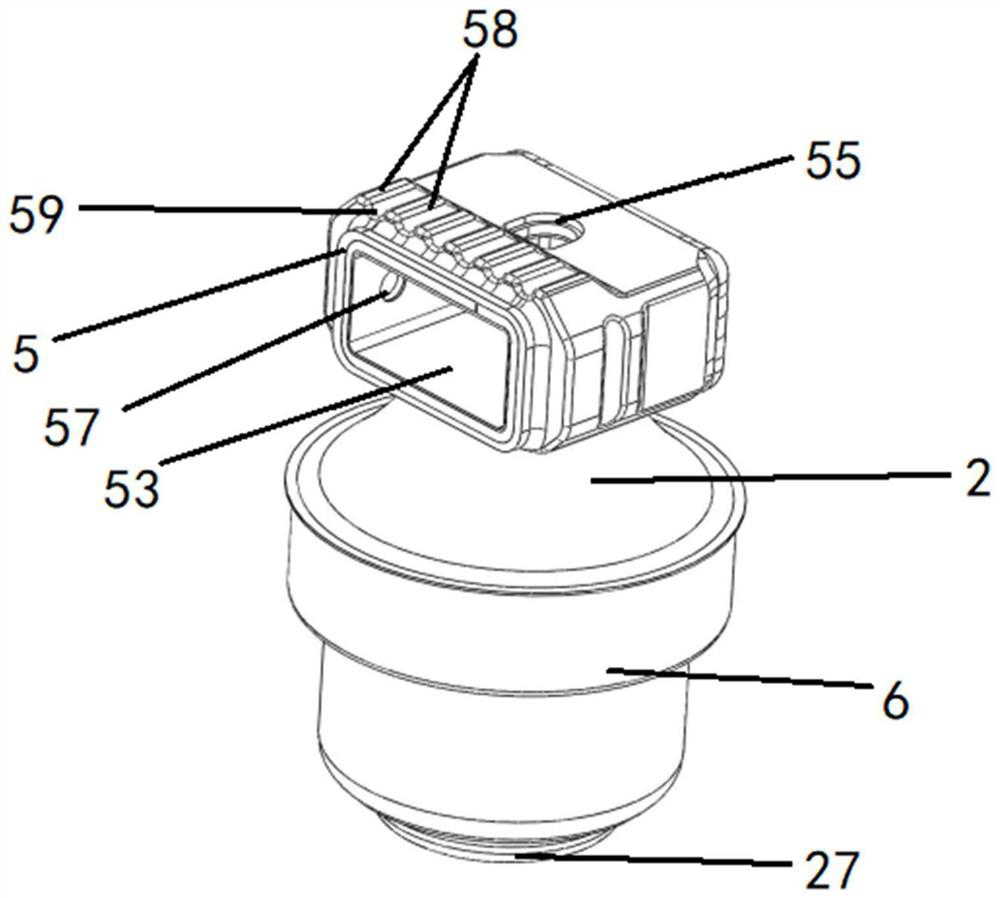
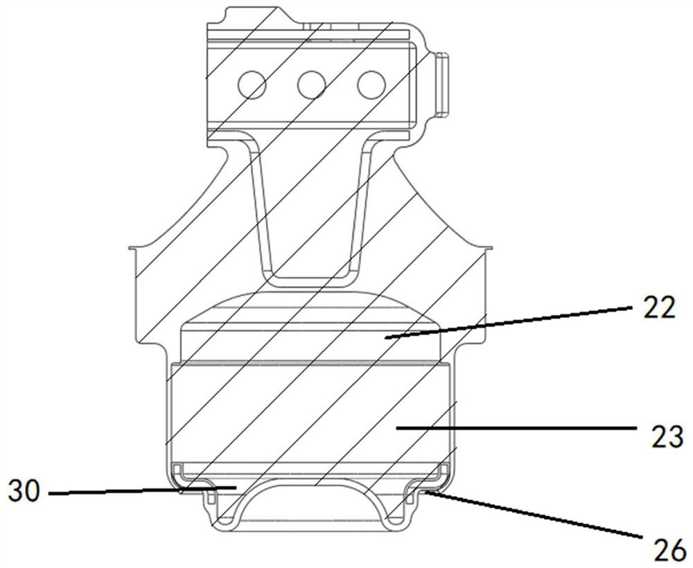
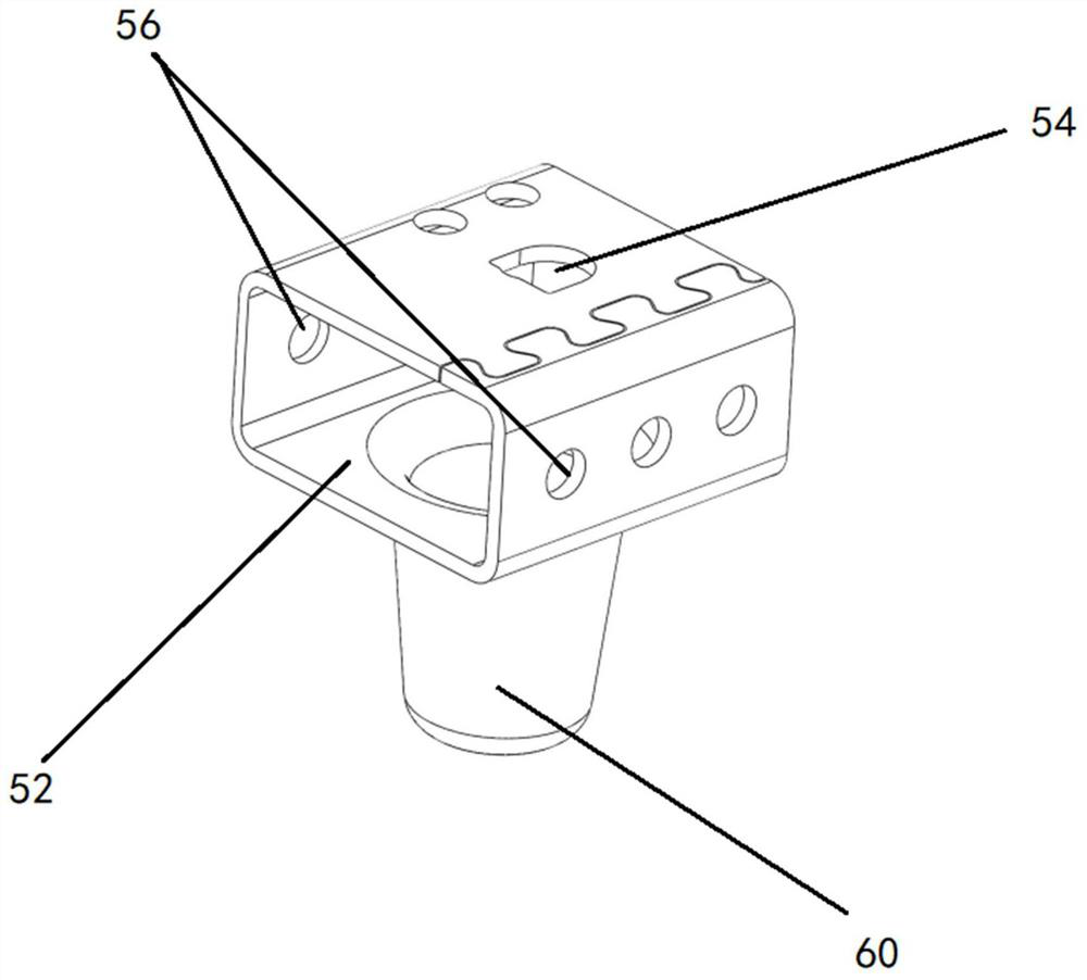
[0042] Such as Figure 1-8As shown, a hydraulic vibration isolation device with double channels 12 includes a valve body 1, and an inner cavity 7 and a flow channel 12 are arranged on the valve body 1. The inner cavity 7 is arranged in the valve body 1, and the flow channel 12 surrounds the valve body. The side of the outer surface of the body 1 is set; the flow channel 12 includes a flow channel inlet 16, a first flow channel outlet 13 and a second flow channel outlet 17, and the flow channel inlet 16 and the second flow channel outlet 17 are arranged on both sides of the flow channel 12 end, the first flow channel outlet 13 is arranged between the flow channel inlet 16 and the second flow channel outlet 17, the first flow channel outlet 13 communicates the flow channel 12 with the inner cavity 7; between the flow channel inlet 16 and the first flow channel outlet 13 It is the first flow channel 14, and the second flow channel 15 is between the first flow channel outlet 13 an...

Embodiment 2

[0059] Such as Figure 11-12 As shown, in this embodiment, a restrictor plate 150 is also provided in the inner cavity, and through holes are distributed on the restrictor plate 150; the decoupling plate covers the upper surface of the restrictor plate 150, and the restrictor plate The horizontal height of 150 is higher than the horizontal height of the outlet of the first flow channel; in this embodiment, the decoupling disc is placed in a position convenient to open through the restrictor plate 150, so that the decoupling disc can be stably opened when the damping fluid moves upward , so as to ensure the shock absorption effect of the present invention, and avoid the decoupling disc from clogging the inner cavity to cause negative pressure in the liquid chamber, thereby causing abnormal cavitation noise, and further improving the riding experience of the vehicle; and the through holes arranged in a distributed manner make The damping fluid is more stable when it passes throu...


PUM


Abstract

The invention discloses a double-runner hydraulic vibration isolation device which comprises a valve body. An inner cavity and runners are arranged on the valve body, the inner cavity is arranged in the valve body, the runners are arranged on the side face of the outer surface of the valve body, and a first runner outlet is formed in the runners so that the inner cavity can communicate with the runners; and the runners comprise the first runner and the second runner, the first runner communicates with the second runner, and the first runner outlet is formed between the first runner and the second runner. The two runners are arranged, the stroke of damping liquid flowing in the first runner is short, and the requirement for large damping of a traditional structure can be met; and when the damping liquid passes through the first runner and then enters the second runner, the stroke is long, the performance of low dynamic stiffness can be generated at the specific frequency (idling), and the vibration isolation effect of an engine during idling is more prominent.

Description

technical field [0001] The invention relates to the field of design and manufacture of shock absorbing devices, and more specifically, relates to a double-channel hydraulic vibration isolating device. Background technique [0002] The hydraulic vibration isolation device is a commonly used vibration isolation device in existing equipment. Compared with other types of vibration isolation devices, the vibration isolation effect of the hydraulic vibration isolation device is more gentle and stable; therefore, it is often used in automobiles. To bring passengers a good and comfortable ride experience; [0003] The traditional hydraulic vibration damping device has only one flow channel, and the liquid flowing in the flow channel will generate large damping, which will increase the dynamic stiffness of the entire hydraulic vibration isolation device, so that the vehicle has better performance when encountering road conditions with large undulations. Shock absorption effect; but ...

Claims


Application Information

Patent Timeline
Patent Type & Authority Applications(China)
IPC IPC(8): F16F13/10
CPCF16F13/101F16F13/103F16F2222/12
Inventor 沈霄峰黄年兵张裕军林雨佳潘兵兵
Owner 建新赵氏科技股份有限公司
Why Eureka
Try Eureka