
Pneumatic spring vibration isolator of air flotation type forward and backward swing concatenation mechanism based on ball head connecting rod

A technology of air springs and ball-end connecting rods, which is used in gas shock absorbers, springs/shock absorbers, mechanical equipment, etc., to achieve the effects of compact structure, improved comprehensive vibration isolation performance, and good vibration isolation performance.

Inactive Publication Date: 2011-05-25
HARBIN INST OF TECH
View PDF5 Cites 15 Cited by
  • Summary
  • Abstract
  • Description
  • Claims
  • Application Information

AI Technical Summary

Problems solved by technology

[0017] In order to solve the technical problems existing in the existing vibration isolator, the present invention proposes an air spring vibration isolator based on the ball-joint link and the air-floating positive and negative pendulum series mechanism to meet the requirements of ultra-low frequency in the field of ultra-precision measurement, processing and assembly debugging. The need for vibration isolation

Method used


Image

  • Pneumatic spring vibration isolator of air flotation type forward and backward swing concatenation mechanism based on ball head connecting rod
  • Pneumatic spring vibration isolator of air flotation type forward and backward swing concatenation mechanism based on ball head connecting rod
  • Pneumatic spring vibration isolator of air flotation type forward and backward swing concatenation mechanism based on ball head connecting rod

Examples


Embodiment Construction

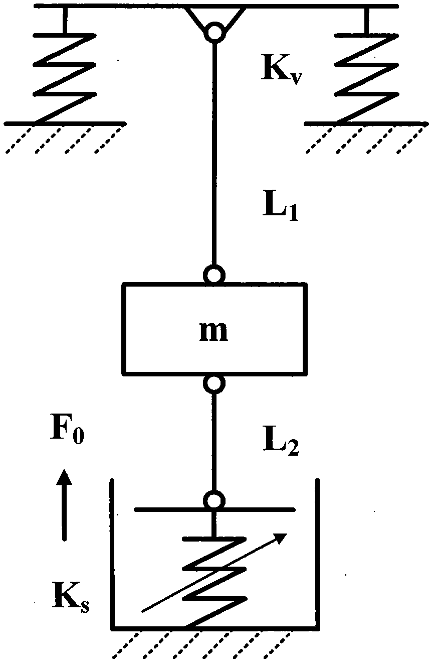
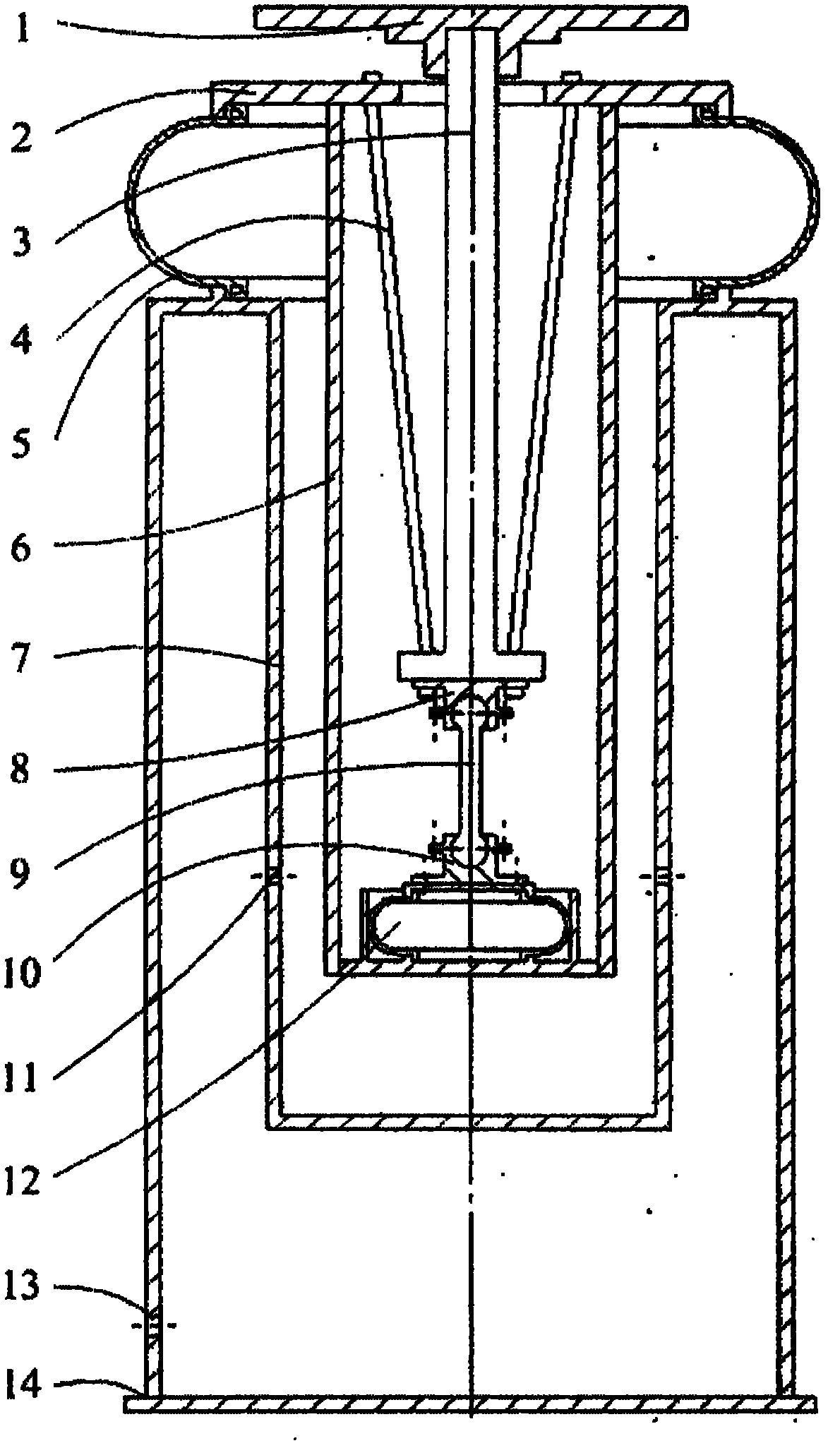
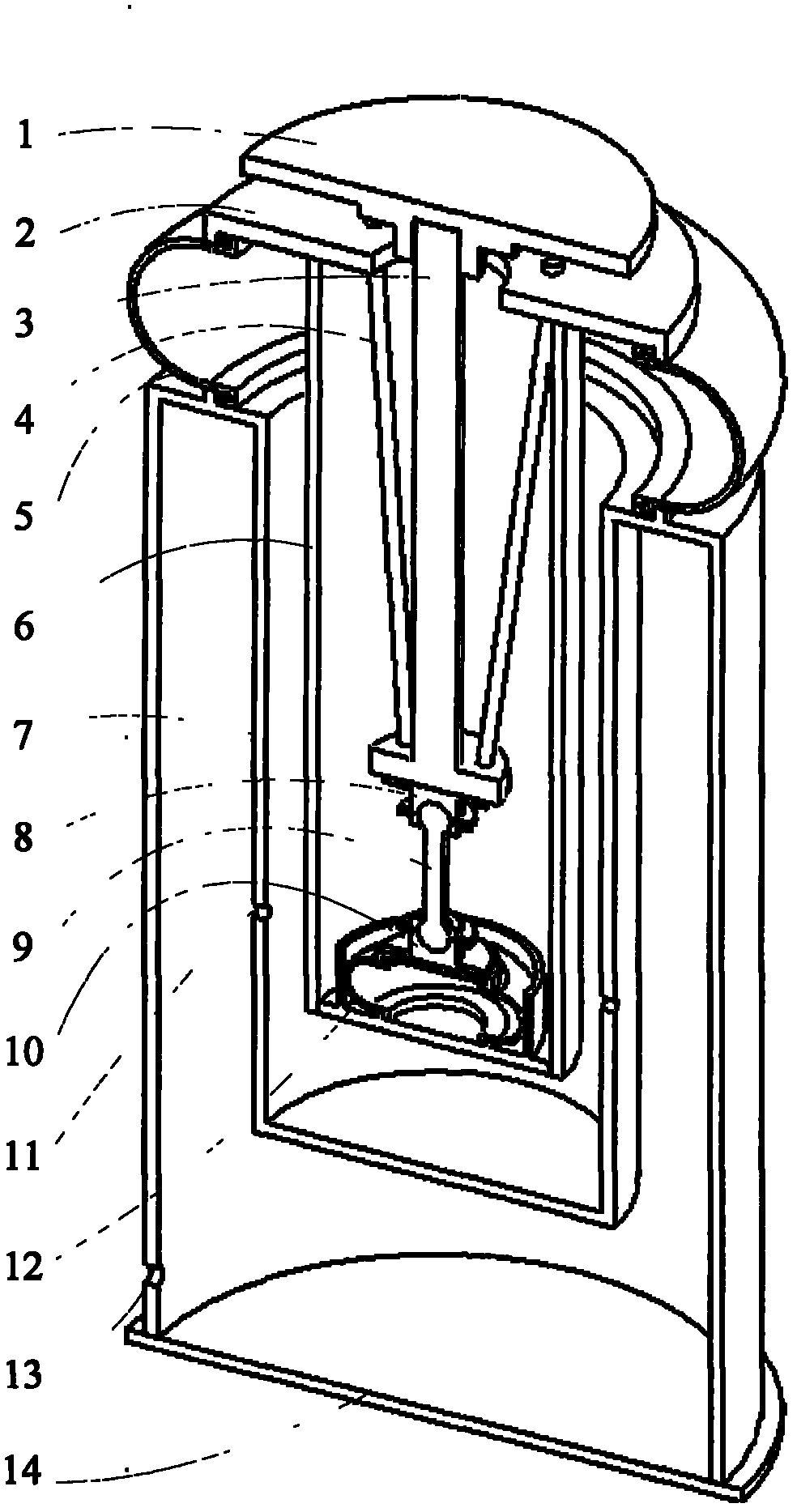
[0036] Specific embodiments of the present invention are described in detail below in conjunction with accompanying drawings, as figure 2 , image 3 and Figure 4 As shown, an embodiment of the air spring isolator of the present invention is shown.

[0037] The air spring vibration isolator is equipped with an inner cylinder 6 inside the outer cylinder 7, and the air spring airbag 5 is set outside the upper end of the inner cylinder 6. The outer cylinder 7 is sealed and connected with the lower end of the air spring airbag 5 through its upper end boss, and the inner cylinder 6 The annular cover plate 2 affixed to its upper end is sealed and connected with the upper end of the air spring airbag 5 , the air inlet 13 is arranged on the outer wall of the outer cylinder 7 , and a group of throttle holes 11 arranged in a circle are arranged on the inner wall of the outer cylinder 7 . The lower end is sealed and equipped with a circular bottom plate 14, and the support rod 3 passe...


PUM


Abstract

The invention relates to a pneumatic spring vibration isolator of an air flotation type forward and backward swing concatenation mechanism based on a ball head connecting rod, which belongs to the ultra-precise measurement and processing field. An inner cylinder is assembled in an outer cylinder of the vibration isolator, an air bag for an air spring is sleeved outside the upper end of the inner cylinder, a support rod is arranged in the chamber of the inner cylinder after penetrating through an annular cover plate, and the upper end and the lower end of a diagonal cable wire are respectively fixed with the annular cover plate and the support rod to form a single swing mechanism; an upper ball seat and a lower ball seat are respectively arranged on the lower end of the support rod and the upper end surface of the air spring, and the upper end and the lower end of the ball head connecting rod are respectively arranged in the upper ball seat and the lower ball seat to form a reversed swing mechanism; and the single swing mechanism and the reversed swing mechanism form the forward and backward swing concatenation mechanism. The air spring is used as a reversed swing spring, and the rigidity of the reversed swing spring can be changed by continuously adjusting the internal pressure of the air spring, thereby the real time adjustment of the rigidity of the forward and backward swing concatenation mechanism can be realized to meet requirements of different operating conditions. The pneumatic spring vibration isolator is introduced by the forward and backward swing concatenation mechanism, which not only enhances the comprehensive vibration isolation performance of the isolator, but also overcomes many disadvantages of other types of isolators.

Description

technical field [0001] The invention belongs to the field of ultra-precision measurement and processing, and in particular relates to an air spring vibration isolator based on an air-floating positive and negative pendulum series mechanism based on a ball-joint link. Background technique [0002] A vibration isolation device with excellent performance is one of the key technologies for ultra-precision measurement and processing. The air spring vibration isolator has the advantages of good ultra-low frequency vibration isolation performance, high bearing capacity, low equivalent stiffness, natural frequency insensitivity to load changes, easy system implementation, and low energy consumption. With the development of ultra-precision measurement and processing technology With the development of , nanotechnology and VLSI manufacturing technology, air spring isolators have been more and more widely used. Vibration isolation of a measurement frame such as a photolithography machi...

Claims


Application Information

Patent Timeline
IPC IPC(8): F16F15/023F16F15/02F16F9/05
Inventor 谭久彬夏超王雷闻荣伟杨文国
Owner HARBIN INST OF TECH
Learn More