
Exhaust valve

An exhaust valve and valve core technology, applied in the direction of lift valve, valve details, valve device, etc., can solve the problems of reducing the effective intake area of ​​the intake port, reducing the exhaust efficiency of the valve, and hindering the exhaust speed, etc. Achieve the effect of improving utilization efficiency, fast exhaust speed, and increasing exhaust speed

Pending Publication Date: 2022-01-11
ZHONGSHAN TAILI HOUSEHOLD PROD MFG
View PDF1 Cites 0 Cited by
  • Summary
  • Abstract
  • Description
  • Claims
  • Application Information

AI Technical Summary

Problems solved by technology

However, there is a large guide column at the bottom center of the valve core of this type of air valve, which prevents the gas from entering from the center of the air inlet, but forces the gas to enter only from both sides of the air inlet.
On the one hand, the central guide column significantly reduces the effective air intake area of ​​the air intake, resulting in a reduction in the exhaust efficiency of the valve; on the other hand, studies have shown that the speed of gas entering from the center of the air intake The edge air intake speed is fast, and the center guide column prevents the gas from entering from the center of the air inlet, which seriously hinders the exhaust speed

Method used


Image

  • Exhaust valve
  • Exhaust valve
  • Exhaust valve

Examples


Embodiment Construction

[0033] In order to enable those skilled in the art to better understand the technical solutions of the present invention, the present invention will be further described in detail below in conjunction with the accompanying drawings and specific embodiments.

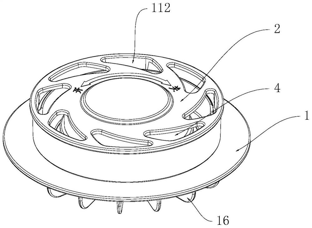
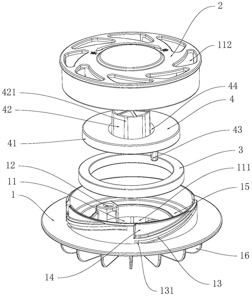
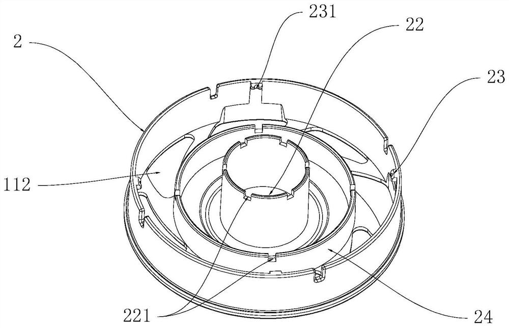
[0034] Such as Figure 1 to Figure 4 An exhaust valve is shown, comprising:

[0035] A seat body 1, the seat body 1 is provided with an inner cavity 11, and the bottom of the inner cavity 11 is provided with an air inlet 111 and an air outlet 112;

[0036] The upper cover 2 is installed on the base body 1 and can be raised and lowered relative to the base body 1;

[0037] The movable spool 4 is arranged between the upper cover 2 and the bottom of the inner cavity 11 and can lift between the two to open or close the air inlet 111, and the movable spool 4 includes a plate-shaped or cover-shaped spool subject 41;

[0038] Between the top of the upper cover 2 and the upper part of the movable spool 4, a first guide structu...


PUM


Abstract

The invention discloses an exhaust valve. The exhaust valve comprises a seat body, an upper cover and a movable valve element, a first guide structure for guiding ascending and descending of the movable valve element is arranged between the top of the upper cover and the upper part of the movable valve element, and a second guide structure for guiding ascending and descending of the movable valve element is arranged between the bottom of an inner cavity and the lower part of the movable valve element; the second guide structure comprises an insertion column arranged at the bottom of the movable valve element and a guide hole formed in the bottom of the inner cavity, the insertion column is inserted into the guide hole, and the guide hole deviates from the center of an air inlet. The exhaust valve has the advantages that the hard valve element moves up and down smoothly, the production technology is simple, the sealing performance is stable, the air inlet and exhaust speed is high, and the volume is small.

Description

technical field [0001] The invention relates to the technical field of gas valves, in particular to an exhaust valve. Background technique [0002] At present, there are various structures of air valves on the market. The common one is that the soft rubber air plug moves up and down to achieve the exhaust effect. However, it is difficult to control the defect rate of the finished product due to the flexible material during the manufacture of soft rubber, and a slight deformation is very effective. The role of the valve. [0003] Publication number is CN 213017893 U utility model patent, discloses a kind of patent of one-way valve and vacuum storage bag. The finished hard rubber valve core is easier to make and shape, and the yield rate is high, and the soft rubber and hard rubber valve core can also be well sealed. At the same time, because it is hard rubber, the valve can be enlarged in size, so as to exhaust faster. However, the center of the bottom of the spool of this...

Claims


Application Information

Patent Timeline
Patent Type & Authority Applications(China)
IPC IPC(8): F16K1/36F16K1/42F16K1/32F16K31/12
CPCF16K1/36F16K1/42F16K1/32F16K31/12
Inventor 石正兵
Owner ZHONGSHAN TAILI HOUSEHOLD PROD MFG
Learn More