Device and method for measuring foam size distribution

A size distribution and foam technology, applied in the field of foam testing devices, can solve the problems of testing affecting foam diameter distribution, difficulty in extracting foam images, blurring of foam images, etc. The effect of image size

Active Publication Date: 2022-01-11
XI'AN PETROLEUM UNIVERSITY
View PDF7 Cites 0 Cited by
  • Summary
  • Abstract
  • Description
  • Claims
  • Application Information

AI Technical Summary

Problems solved by technology

[0005] The inventors have found that the widely used optical method in the laboratory often uses microscope technology to observe the morphological decay process of foam, but in practical applications, after using the above method to generate a certain volume and height of foam, when directly observed through a microscope, it is often because the lens Due to the limitation of focal length, a large number of background bubbles appear during shooting, resulting in blurred foam images; the size of the foam is relatively small and the foam structure is repeatedly stacked, it is often difficult to extract a clear foam image during image post-processing, which affects the follow-up Test of Foam Diameter Distribution

Method used


Image

  • Device and method for measuring foam size distribution
  • Device and method for measuring foam size distribution
  • Device and method for measuring foam size distribution

Examples


Embodiment 1

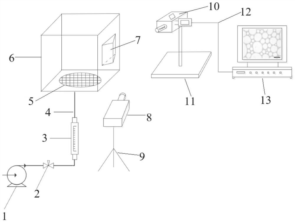
[0039] In a typical embodiment of the present invention, such as Figure 1-Figure 2 As shown, a device for measuring the size distribution of foam is proposed, including a foaming unit for generating foam, a foam collection unit for collecting foam, an optical path conversion unit for light conversion, and an optical imaging unit for optical imaging. An imaging unit and an image acquisition unit.

[0040] Wherein, the lower end of the bubble collection unit is connected to the foaming unit, the optical path conversion unit is arranged on the side of the bubble collection unit, the optical imaging unit is arranged on one side of the optical path conversion unit, and the image acquisition unit is connected to the optical imaging unit.

[0041] Specifically, this embodiment adopts the bubbling method, and the foaming unit is composed of a gas pump 1, a gas phase valve 2, a gas flow meter 3, an air guide tube 4 and an air stone plate 5, and the gas pump 1 passes through the air gu...

Embodiment 2

[0061] In another typical embodiment of the present application, the method for measuring the device for measuring foam size distribution as described in Example 1 is provided, and the specific process is as follows:

[0062] Step 1: Connect the gas pump 1, the gas phase valve 2, and the gas flow meter 3 to the bottom of the gas stone plate 5 through the air guide tube 4;

[0063] Step 2: Pour the configured foam liquid into the transparent glass box 6 from the top, open the gas pump 1 and the gas phase valve 2, control the gas flow, and after a certain height of foam is generated in the transparent glass box 6, turn off the gas pump 1 and the gas phase valve 2. Gas phase valve 2;

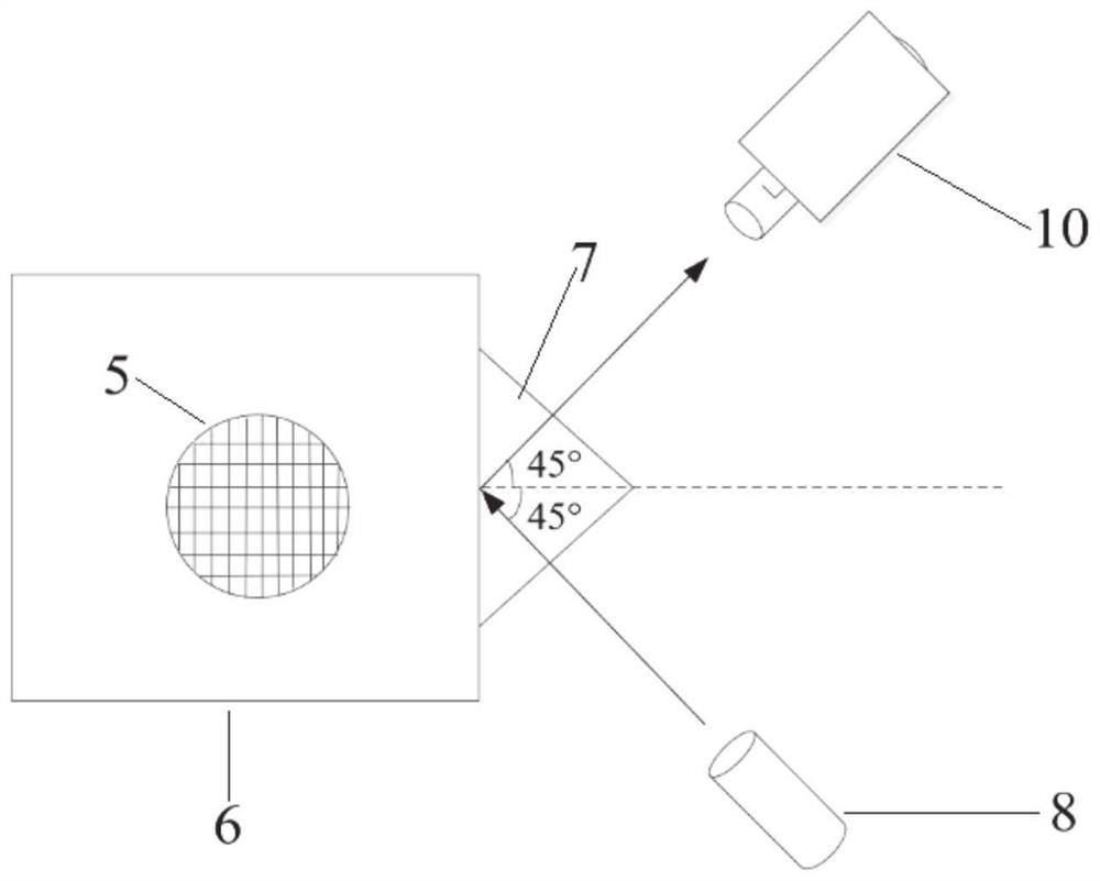
[0064] Step 3: Fix the right-angled prism 7 on the surface of the transparent glass box 6, align the fill light 8 with the left side of the right-angled prism 7 along the horizontal 45°, align the lens of the microscope 10 with the right side of the right-angled prism 7 along the horizontal 45°, an...


PUM


Abstract

The invention discloses a device and method for measuring foam size distribution, and belongs to the technical field of foam testing devices. A light path conversion unit is arranged on the side portion of a foam collecting unit to refract light, a clear bubble distribution image is obtained through light refraction, distribution of bubble diameters can be conveniently tested, and a problem that a large number of background bubbles easily appear during microscope shooting is solved. According to the invention, the device comprises a foaming unit; a bubble collecting unit, wherein foam generated by the foaming unit is supplied to the bubble collecting unit; a light path conversion unit arranged at the side part of the bubble collecting unit; and an optical imaging unit which is arranged opposite to the light path conversion unit, wherein a bubble distribution image is obtained in the optical imaging unit after the light is refracted by the light path conversion unit.

Description

technical field [0001] The invention relates to the technical field of foam testing devices, in particular to a device and method for measuring foam size distribution. Background technique [0002] The statements herein merely provide background information related to the present invention and do not necessarily constitute prior art. [0003] As an important substance in the chemical industry, foam has been widely used in many fields, such as secondary exploitation of petroleum, foam fire extinguishing, ore flotation, foam decontamination, and wastewater treatment. Among them, the stability of foam is in An important property in practical applications, the stability of foam refers to the persistence of the generated foam. In different application fields, the performance requirements of the foam are also different, and the foam with poor stability will increase the burst rate of the bubbles. From a macroscopic point of view, one main method is to characterize the stability ...

Claims


Application Information

Patent Timeline
Patent Type & Authority Applications(China)
IPC IPC(8): G01B11/08
CPCG01B11/08
Inventor 张亦翔蒋海岩朱建鲁李玉星
Owner XI'AN PETROLEUM UNIVERSITY
Why Eureka
Try Eureka