Vibration mirror-based high-speed virtual camera system, observation method and equipment

A virtual camera and high-speed camera technology, applied in the field of photography, can solve the problem of not being able to observe multiple objects in high-definition, and achieve the effect of low cost, small size and high precision

Active Publication Date: 2022-05-17
INST OF AUTOMATION CHINESE ACAD OF SCI
View PDF4 Cites 0 Cited by
  • Summary
  • Abstract
  • Description
  • Claims
  • Application Information

AI Technical Summary

Problems solved by technology

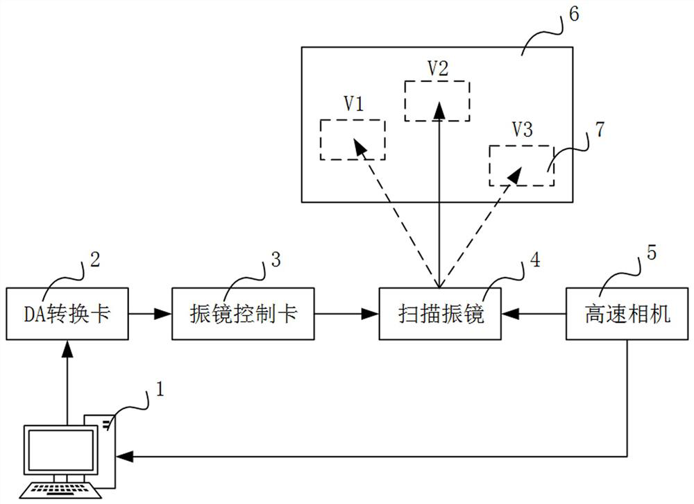
[0006] In order to solve the above-mentioned problems in the prior art, that is, in order to solve the problem that the prior art cannot observe multiple objects in high-definition at a long distance in real time, the present invention proposes a high-speed virtual camera system based on vibrating mirrors, which includes : computer, D\A signal converter, vibrating mirror control board, vibrating mirror unit, high-speed camera; said computer, said D\A signal converter, said vibrating mirror control board, said vibrating mirror unit, said The high-speed cameras are sequentially connected through a communication link;

Method used


Image

  • Vibration mirror-based high-speed virtual camera system, observation method and equipment
  • Vibration mirror-based high-speed virtual camera system, observation method and equipment
  • Vibration mirror-based high-speed virtual camera system, observation method and equipment

Examples


Embodiment Construction

[0053] In order to make the purpose, technical solutions and advantages of the embodiments of the present invention clearer, the technical solutions in the embodiments of the present invention will be clearly and completely described below in conjunction with the drawings in the embodiments of the present invention. Obviously, the described embodiments It is a part of embodiments of the present invention, but not all embodiments. Based on the embodiments of the present invention, all other embodiments obtained by persons of ordinary skill in the art without making creative efforts belong to the protection scope of the present invention.

[0054] The application will be further described in detail below in conjunction with the accompanying drawings and embodiments. It should be understood that the specific embodiments described here are only used to explain related inventions, rather than to limit the invention. It should be noted that, in the case of no conflict, the embodime...


PUM


Abstract

The invention belongs to the field of imaging, and in particular relates to a vibrating mirror-based high-speed virtual camera system, observation method and equipment, aiming to solve the problem that the prior art cannot observe multiple objects in real time at a long distance with high definition. The system of the present invention includes: a computer, used to obtain the position to be observed on the set observation plane; D\A signal converter, used to convert the received digital signal into an analog signal; the vibrating mirror control board, used to convert the received Analyze the analog signal of the scanning electron microscope into a control command; the vibrating mirror unit is used to control the rotation of the lens of the scanning electron microscope according to the control command, obtain the optical signal of the position to be observed, and reflect it; the high-speed camera is used to reflect the optical signal of the scanning electron microscope Take pictures, obtain high-definition images of the positions to be observed on the set observation plane, and send them to the computer. The invention can realize real-time and high-definition shooting of multiple distant targets.

Description

technical field [0001] The invention belongs to the field of imaging, and in particular relates to a vibrating mirror-based high-speed virtual camera system, observation method and device. Background technique [0002] In the process of shooting long-distance objects, due to the limitation of the focal length of ordinary cameras, short-focus cameras can obtain a larger field of view, usually with a viewing angle of more than 60 degrees, but cannot describe detailed information, and it is blurry when shooting long-distance images; telephoto cameras It is clearer and retains more details when shooting distant objects, but the field of view is narrow, usually within 15 degrees, and only small-scale scene observation can be performed. [0003] In order to shoot a large range of long-distance objects with high definition, two methods are mainly used at present. One is to arrange a large number of telephoto cameras in an orderly manner to form a camera array. In the later stage, ...

Claims


Application Information

Patent Timeline
Patent Type & Authority Patents(China)
IPC IPC(8): G06T7/80G06T7/70
CPCG06T7/80G06T7/70G06T2207/30244
Inventor 顾庆毅陈梦娟李志凯
Owner INST OF AUTOMATION CHINESE ACAD OF SCI
Why Eureka
Try Eureka