
Visual monitoring and shooting device for power transmission line

A power transmission line and monitoring technology, which is applied in the direction of TV, color TV, closed-circuit television system, etc., can solve the problems of power transmission equipment position and angle deviation, potential safety hazards, and equipment failure to work normally, so as to ensure normal use and convenient adjustment Effect

Pending Publication Date: 2022-04-12
STATE GRID JIANGSU ELECTRIC POWER CO LIANYUNGANG POWER SUPPLY CO +1
View PDF0 Cites 0 Cited by
  • Summary
  • Abstract
  • Description
  • Claims
  • Application Information

AI Technical Summary

Problems solved by technology

Since the high-voltage towers of transmission lines are mostly located in natural environments such as mountains and fields far away from people, they are easily affected by harsh environments or invaded by external objects such as birds during long-term use, resulting in position and angle deviation of transmission equipment. The equipment cannot work normally, and the transmission line cannot be monitored. When there is a problem with the transmission line, there are certain safety hazards, and it is not convenient for workers to adjust the equipment.

Method used


Image

  • Visual monitoring and shooting device for power transmission line
  • Visual monitoring and shooting device for power transmission line
  • Visual monitoring and shooting device for power transmission line

Examples


Embodiment Construction

[0018] The following will clearly and completely describe the technical solutions in the embodiments of the present invention with reference to the accompanying drawings in the embodiments of the present invention. Obviously, the described embodiments are only some, not all, embodiments of the present invention. Based on the embodiments of the present invention, all other embodiments obtained by persons of ordinary skill in the art without making creative efforts belong to the protection scope of the present invention.

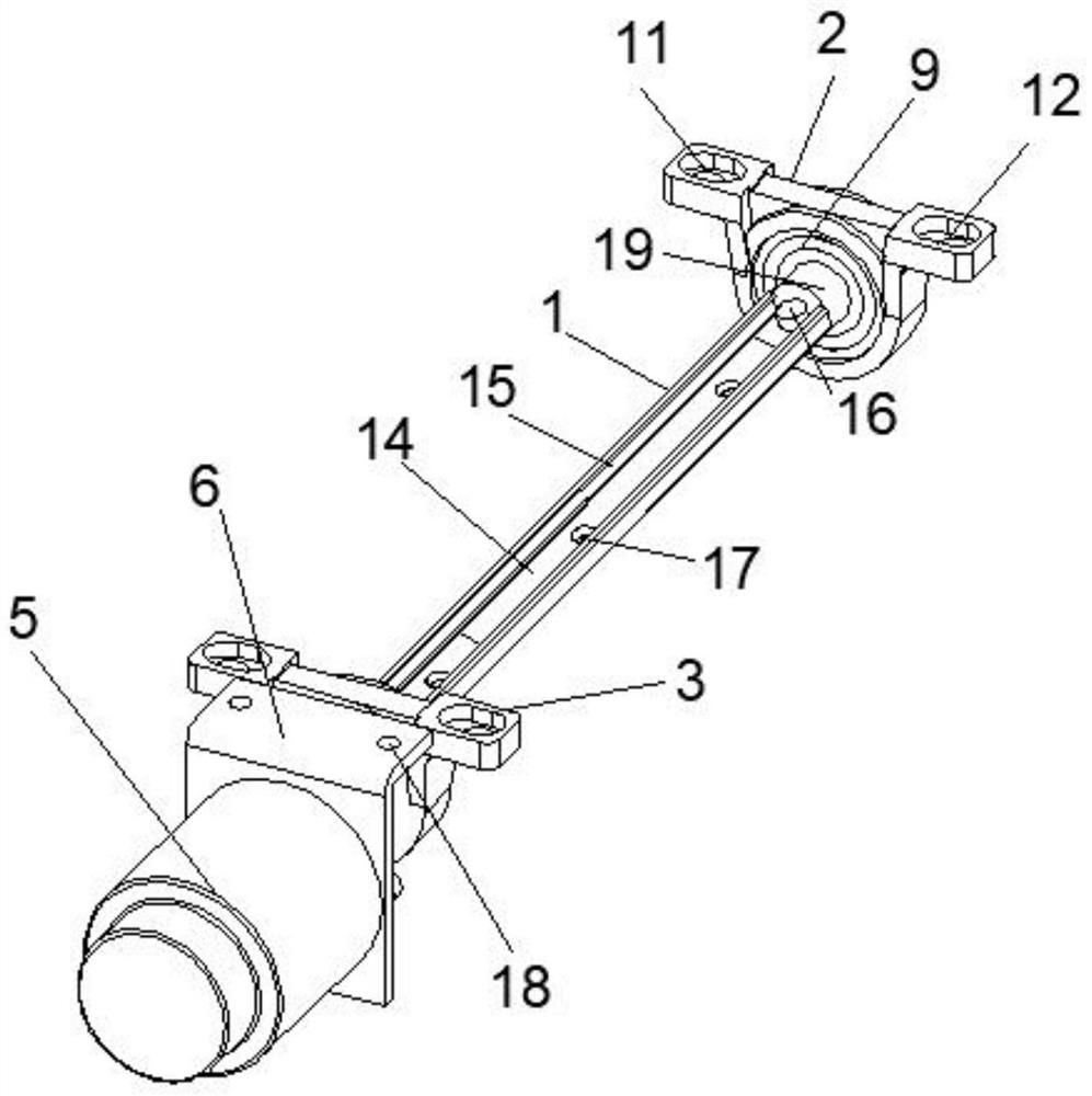
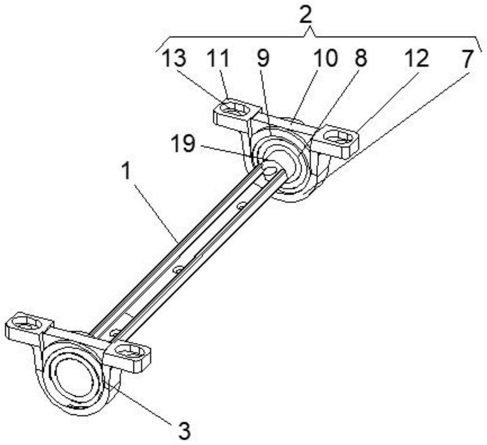
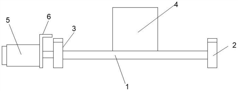
[0019] Such as Figure 1-4 As shown, the present invention provides a technical solution: a visual monitoring device for power transmission lines, including a connecting body 1, one end of the connecting body 1 is provided with a first connecting seat 2, and the other end of the connecting body 1 is provided with a second connecting seat 3. The first connecting seat 2 and the second connecting seat 3 are rotationally connected with the connecting body 1, and t...


PUM


Abstract

The invention discloses a power transmission line visual monitoring and shooting device which comprises a connecting body, one end of the connecting body is provided with a first connecting seat, the other end of the connecting body is provided with a second connecting seat, and the first connecting seat and the second connecting seat are rotationally connected with the connecting body. The two ends of the connecting body are correspondingly installed at the centers of the first connecting base and the second connecting base respectively, a video monitor is placed on the connecting body, a driver is arranged on one side of the connecting body and located on one side of the second connecting base, a connecting plate is arranged on the driver, and the connecting plate is used for fixing the driver. The first connecting base comprises a sleeve shell, a fixing ring, a bearing, a limiting stop lever, a first connecting lug and a second connecting lug, and one end of the connecting body is fixedly connected with the fixing ring. According to the visual monitoring and shooting device for the power transmission line, the video monitor can be conveniently adjusted, the video monitor can conveniently monitor and shoot the power transmission line in real time, adjustment is convenient, and normal use of the monitored power transmission line is guaranteed.

Description

technical field [0001] The invention relates to the technical field of monitoring equipment for transmission lines, in particular to a visual monitoring device for transmission lines. Background technique [0002] The transmission line is realized by using a transformer to boost the electric energy generated by the generator, and then connecting it to the transmission line through control equipment such as a circuit breaker. In the structural form, the transmission line is divided into overhead transmission lines and cable lines. On the ground, the overhead transmission line is composed of line towers, wires, insulators, line fittings, guy wires, tower foundations, grounding devices, etc., and is erected on the ground. Using insulators and air-insulated power lines, according to the nature of the transmission current, power transmission is divided into AC transmission and DC transmission. Since the high-voltage towers of transmission lines are mostly located in natural envi...

Claims


Application Information

Patent Timeline
Patent Type & Authority Applications(China)
IPC IPC(8): H02G1/02F16M11/04F16M11/10F16M11/18H04N5/232H04N7/18
Inventor 张真卿吴昊朱宏伟房帅徐帆钱开吉王笃乐陈永娟
Owner STATE GRID JIANGSU ELECTRIC POWER CO LIANYUNGANG POWER SUPPLY CO
Learn More