A multi-well two-phase flow metering skid and its metering method

A metering method and technology of metering skids, which are applied in the direction of testing/calibrating volume flow, volume/mass flow generated by mechanical effects, and detecting dynamic effects of fluid flow, etc., which can solve the problem that the separator occupies a large area and cannot produce a single well. Real-time dynamic monitoring and other issues to achieve the effect of reducing labor costs, reducing inspection and maintenance costs, and facilitating operation

Active Publication Date: 2022-03-29
四川凌耘建科技有限公司 +1
View PDF13 Cites 0 Cited by
  • Summary
  • Abstract
  • Description
  • Claims
  • Application Information

AI Technical Summary

Problems solved by technology

[0005] No matter it is the first or the second method, it is inseparable from the separator to separate the gas and liquid for measurement, and the separator occupies a large area, neither of the two methods can perform real-time dynamic monitoring of single well productivity

Method used


Image

  • A multi-well two-phase flow metering skid and its metering method
  • A multi-well two-phase flow metering skid and its metering method
  • A multi-well two-phase flow metering skid and its metering method

Examples


Embodiment 1

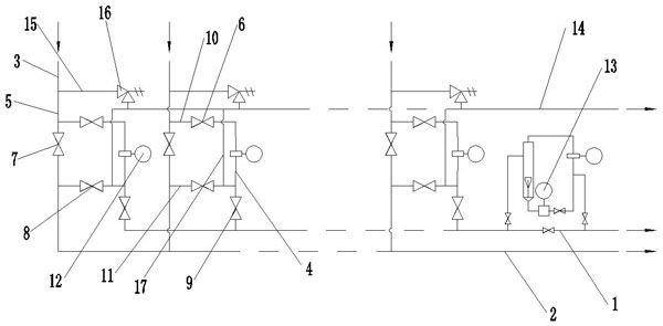
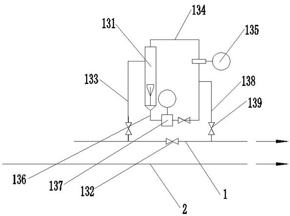
[0057] Such as figure 1 and figure 2 As shown, a multi-well two-phase flow metering skid includes a first production pipeline 1, a second production pipeline 2 and several wellhead connecting pipelines 3 respectively connected to the wellhead, and each of the wellhead connecting pipelines 3 are all communicated with the second production pipeline 2 through the second production connection pipeline 5, each of the second production connection pipelines 5 is provided with a second control valve 7, and each of the second production connection pipelines 5 is respectively provided with a first transition pipeline 10 and a second transition pipeline 11 communicating with the second production connection pipeline 5 from one end close to the wellhead connection pipeline 3 to one end far away from the wellhead connection pipeline 3. A transition line 10 and a second transition line 11 are connected to the second production connection line 5 respectively at both ends of the second cont...

Embodiment 2

[0061] Such as figure 1 and figure 2 As shown, on the basis of the above-mentioned embodiments, a pressure relief pipeline 14 is also included, and the several wellhead connecting pipelines 3 communicate with the pressure relief pipeline 14 through the first pressure relief connecting pipeline 15 .

[0062] In order to ensure the safety of the pipeline, the metering skid is also equipped with a pressure relief pipeline 14, and each wellhead connection pipeline 3 is connected to the pressure relief pipeline 14 through the first pressure relief connection pipeline 15. When the fluid pressure is too large, it can be Perform pressure relief.

Embodiment 3

[0064] Such as figure 1 and figure 2 As shown, on the basis of the above embodiments, each of the pressure relief pipelines 14 is provided with a safety valve 16 .

[0065] A safety valve 16 is provided to automatically open and release pressure when the fluid pressure is too high.


PUM


Abstract

The invention discloses a multi-well type two-phase flow metering skid, which belongs to the field of fluid metering and includes a first production pipeline, a second production pipeline and several wellhead connecting pipelines, each of which is passed through the first wellhead connecting pipeline. The second production connection pipeline communicates with the second production pipeline, each of the second production connection pipelines is provided with a second control valve, and each of the second production connection pipelines is respectively provided with a first transition pipeline and a The second transition pipeline, the first transition pipeline and the second transition pipeline are respectively provided with a first control valve and a third control valve, and the first transition pipeline and the second transition pipeline are provided with a first production A connecting pipeline, a two-phase flowmeter is arranged on the first production connecting pipeline between the connection between the first transition pipeline and the second transition pipeline and the first production connecting pipeline, and the first production connecting pipeline A fourth control valve is arranged on the pipeline. The invention can measure the two-phase flow flow, and can perform online self-calibration for each two-phase flow meter.

Description

technical field [0001] The invention belongs to the field of fluid metering, and in particular relates to a multi-well two-phase flow metering skid and a metering method thereof. Background technique [0002] In the process of oil and gas production, the measurement of two-phase flow at the wellhead is a commonly recognized problem at home and abroad. Currently, there are two forms of production and transportation measurement: [0003] 1. After a single well is separated by a separator, gas-liquid single-phase metering is performed; [0004] 2. Through the flow control of the valve group, after the multi-wells enter the separator for separation, the gas-liquid single-phase metering is performed. [0005] No matter it is the first or the second method, it is inseparable from the separator to separate the gas and liquid for measurement, and the separator occupies a large area. Neither of the two methods can perform real-time dynamic monitoring of the productivity of a single ...

Claims


Application Information

Patent Timeline
Patent Type & Authority Patents(China)
IPC IPC(8): G01F1/32G01F25/10
Inventor 雍登健谢永强刘长艳丁奕汪怡佳杜卞王良贵胡忠伟吴西林
Owner 四川凌耘建科技有限公司
Why Eureka
Try Eureka