
Computer mainboard firmware function testing device

A technology for functional testing and motherboards, which is used in measuring devices, measuring device casings, and environmental/reliability testing. The effect of excessive heat and accurate test data

Active Publication Date: 2022-01-11
深圳市微特精密科技股份有限公司
View PDF7 Cites 2 Cited by
  • Summary
  • Abstract
  • Description
  • Claims
  • Application Information

AI Technical Summary

Problems solved by technology

[0002] When testing the operating data of the computer motherboard, generally a CPU is inserted on the computer motherboard, the test system is connected to the computer motherboard, the power is turned on, and the computer motherboard and CPU start to test and run, and the computer motherboard and CPU are recorded through the test system. Cooperate with the running time data, and obtain key performance parameters such as the running stability of the computer motherboard and the compatibility with the CPU through the running data. However, in the existing testing technology, there are also the following shortcomings: 1. The computer motherboard and the CPU During the long-term test operation, a large amount of heat will be generated. If the heat is too high, the computer motherboard and CPU will be burned; 2. It is impossible to simulate the operating environment of the computer motherboard in the computer. 3, can not simulate the operation status of computer motherboard and CPU in high temperature and low temperature environment, carry out high and low temperature resistance test to computer motherboard; Therefore, the present invention proposes a kind of computer motherboard firmware function testing device

Method used


Image

  • Computer mainboard firmware function testing device
  • Computer mainboard firmware function testing device
  • Computer mainboard firmware function testing device

Examples


Embodiment Construction

[0066] In order to further explain the technical means and effects of the present invention to achieve the intended purpose of the invention, the specific implementation, structure, features and effects of the present invention will be described in detail below in conjunction with the accompanying drawings and preferred embodiments.

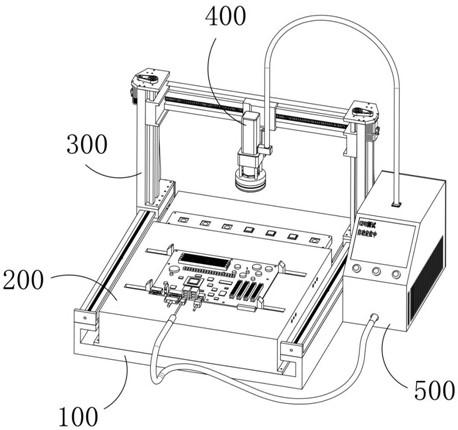
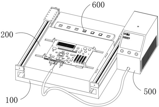
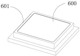
[0067] Such as figure 1 Shown, a kind of computer motherboard firmware function testing device, comprises base frame 100, and support device 200, traction device 300, clamping device 400, test system 500, CPU600 for testing are installed on the base frame 100, wherein, support device 200 is used for positioning and clamping the computer motherboard to be tested, the traction device 300 is used for pulling the clamping device 400 to move in the three-dimensional coordinate system, and the clamping device 400 is used for clamping the CPU600 for testing and pulling it to move to the computer motherboard In the CPU slot of the computer, the clamping ...


PUM


Abstract

The invention relates to a computer mainboard firmware function testing device, belongs to the technical field of mainboard testing, and solves the problems that in the existing computer mainboard testing technology, a large amount of heat is generated, so that a computer mainboard is burnt out, and the running environment of the computer mainboard in a computer cannot be simulated. The high and low temperature resistance of the computer mainboard cannot be tested; according to the scheme, a CPU for testing is clamped in a sealed mode by the clamping device, the clamping device comprises the clamping mechanism used for clamping the CPU for testing and the heat dissipation mechanism used for conducting heat dissipation treatment on the CPU for testing, and the heat dissipation mechanism conducts heat dissipation on the CPU for testing when the circuit mainboard and the CPU for testing run. The invention is prevented from being burnt due to too high heat, the operation environment of the computer mainboard in a computer is simulated, meanwhile, the heat dissipation efficiency of the heat dissipation mechanism is controllable, high-temperature and low-temperature environments can be simulated, and the high-temperature and low-temperature resistance of the computer mainboard can be tested.

Description

technical field [0001] The invention relates to the technical field of mainboard testing, in particular to a computer mainboard firmware function testing device. Background technique [0002] When testing the operating data of the computer motherboard, generally a CPU is inserted on the computer motherboard, the test system is connected to the computer motherboard, the power is turned on, and the computer motherboard and CPU start to test and run, and the computer motherboard and CPU are recorded through the test system. Cooperate with the running time data, and obtain key performance parameters such as the running stability of the computer motherboard and the compatibility with the CPU through the running data. However, in the existing testing technology, there are also the following shortcomings: 1. The computer motherboard and the CPU During the long-term test operation, a large amount of heat will be generated. If the heat is too high, the computer motherboard and CPU wi...

Claims


Application Information

Patent Timeline
IPC IPC(8): G06F11/22G01R31/00G01R1/04
CPCG06F11/2205G01R31/003G01R1/0408
Inventor 程志勇
Owner 深圳市微特精密科技股份有限公司
Learn More