Polishing tool

A technology for grinding tools and bottom plates, which is applied in the direction of manufacturing tools, grinding machines, grinding racks, etc., can solve the problems of elevated center of gravity, low service life, easy breakage, etc., to ensure shock resistance and torsion resistance, and complete machine The effect of size reduction and improved control feeling

Pending Publication Date: 2022-01-14
NANJING CHERVON IND
View PDF0 Cites 0 Cited by
  • Summary
  • Abstract
  • Description
  • Claims
  • Application Information

AI Technical Summary

Problems solved by technology

[0003] The function of the vibrating support in the grinding tool is to support the fuselage and the bottom plate, and make the bottom plate swing with the eccentric parts under the premise of the machine body not moving. The existing vibrating support generally includes a base, a top seat, and a vertical or curved connection. The support bar between the top base and the base, where the base and the top base are fixed to the bottom plate and the fuselage respectively. When vibration occurs due to grinding during work, the vibration support will twist along with the bottom plate. At this time, the vibration support will be subjected to vertical direction and horizontal direction, so if the vibration support is set low, it is easy to break during use and the service life is low; if the vibration support is set high, although the service life is met, the height of the whole machine is high, and then The position of the center of gravity of the whole machine is raised, which affects the portability of the user's operation and is not conducive to improving the user's sense of control

Method used


Image

  • Polishing tool
  • Polishing tool
  • Polishing tool

Examples


Embodiment Construction

[0092] The present invention will be described in detail below in conjunction with the accompanying drawings.

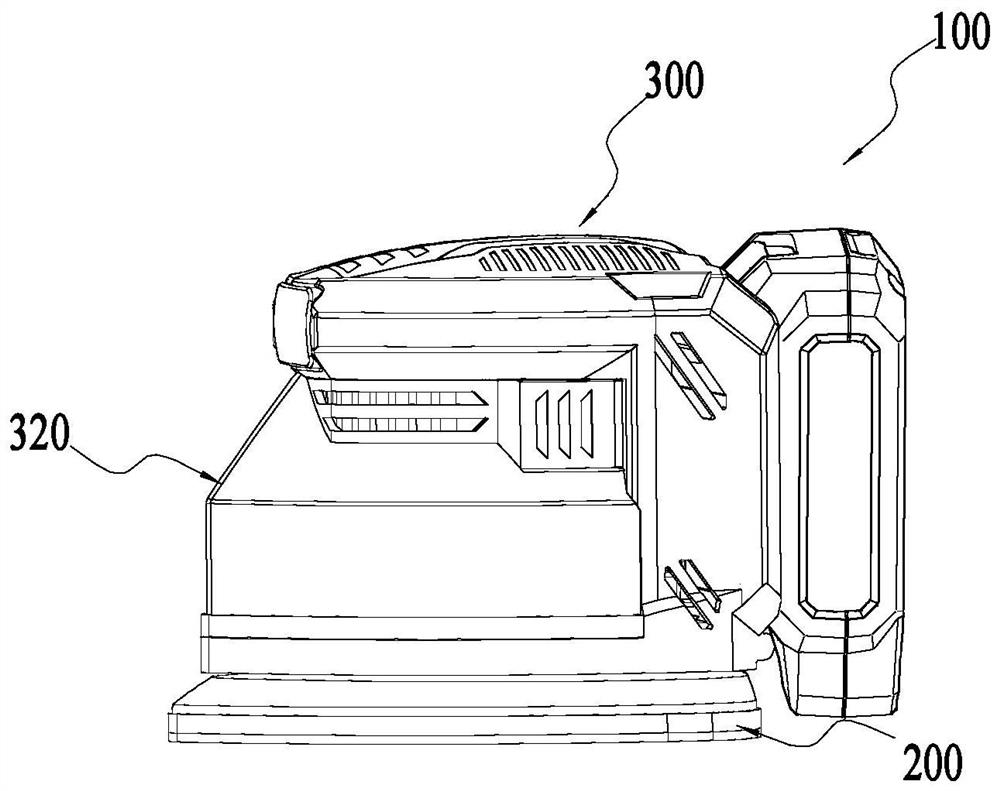
[0093] Such as figure 1 Shown is a grinding tool 100 shown in an embodiment of the present invention. The grinding tool 100 of the embodiment of the present invention is specifically a sander, and more specifically a flat sander that can be held by the user with one or both hands. machine. It can be understood that the grinding tool 100 can be round sand, triangular sand, square sand, special-shaped sand, etc., and only the applicable grinding tools that meet the technical solution of the present invention are within the protection scope of the present invention.

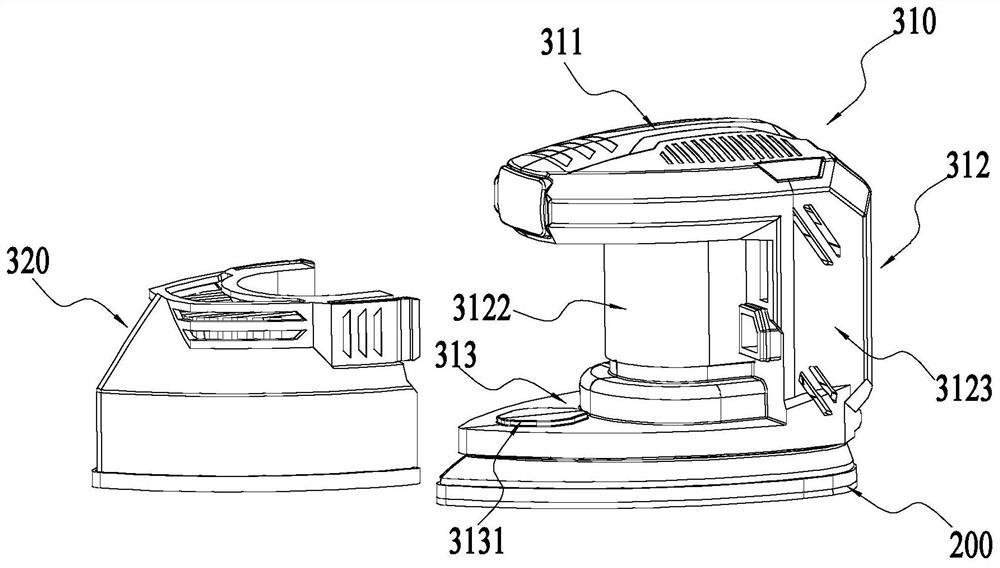
[0094] The grinding tool 100 of the embodiment of the present invention includes a bottom plate assembly 200, a casing assembly 300, a driving mechanism 400, a fan assembly, a dust removal assembly and a power supply. Among them such as figure 2 As shown, the casing assembly includes a body casing 310 ...


PUM

PropertyMeasurementUnit
Axial heightaaaaaaaaaa

Abstract

The invention provides a polishing tool. The polishing tool comprises a bottom plate assembly, a machine shell assembly, a driving mechanism and a supporting frame, wherein the bottom plate assembly comprises a bottom plate and a polishing part fixed to the bottom plate; the machine shell assembly is arranged on the bottom plate and comprises a machine body machine shell; the driving mechanism is arranged to drive the bottom plate assembly to move; the supporting frame is arranged between the machine body machine shell and the bottom plate and comprises a supporting seat, a center releasing part and a floating connecting arm; the supporting seat is arranged between the machine body machine shell and the bottom plate; the center releasing part is directly or indirectly fixedly connected to the bottom plate; and the floating connecting arm is connected between the center releasing part and the supporting seat and allows the supporting seat and the center releasing part to move relatively when the supporting frame is subjected to axial and / or radial acting force.

Description

technical field [0001] The invention relates to the technical field of electric tools, in particular to a grinding tool. Background technique [0002] Grinding tool is a kind of commonly used electric tool, realizes polishing and grinding on the surface of materials such as wood, plastics, stone, metal through the swing of bottom plate. On the basis of satisfying the grinding function, the hand-held grinding tool should usually have a small volume and dead weight, so as to meet the user's expectation of convenient operation and user experience. [0003] The function of the vibrating support in the grinding tool is to support the fuselage and the bottom plate, and make the bottom plate swing with the eccentric parts under the premise of the machine body not moving. The existing vibrating support generally includes a base, a top seat, and a vertical or curved connection. The support bar between the top base and the base, where the base and the top base are fixed to the bottom...

Claims


Application Information

Patent Timeline
IPC IPC(8): B24B23/04B24B41/02B24B55/00
CPCB24B23/04B24B41/02B24B55/00
Inventor 徐中全石灵建刘天亮
Owner NANJING CHERVON IND
Why Eureka
Try Eureka