Mold with good injection molding effect and anti-overflow device for injection mold

An injection mold and anti-overflow technology, which is applied in the field of injection molds, can solve the problems of material heating, affecting the injection molding effect, and the injection speed does not change.

Inactive Publication Date: 2022-01-14
仙居县瑞亨吸塑厂
View PDF1 Cites 0 Cited by
  • Summary
  • Abstract
  • Description
  • Claims
  • Application Information

AI Technical Summary

Problems solved by technology

[0006] The object of the present invention is to provide a mold with good injection molding effect and an anti-overflow device for injection molds, to solve the problem that when the temperature inside the existing channel in the above-mentioned background technology is low, the injection speed of the material does not change, which leads to the leakage of the material The flow speed is fast, and the material cannot be fully heated inside the runner, which affects the later injection molding effect.

Method used


Image

  • Mold with good injection molding effect and anti-overflow device for injection mold
  • Mold with good injection molding effect and anti-overflow device for injection mold
  • Mold with good injection molding effect and anti-overflow device for injection mold

Examples


Embodiment 1

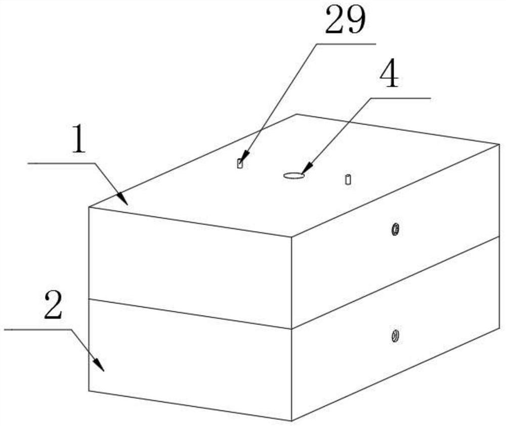
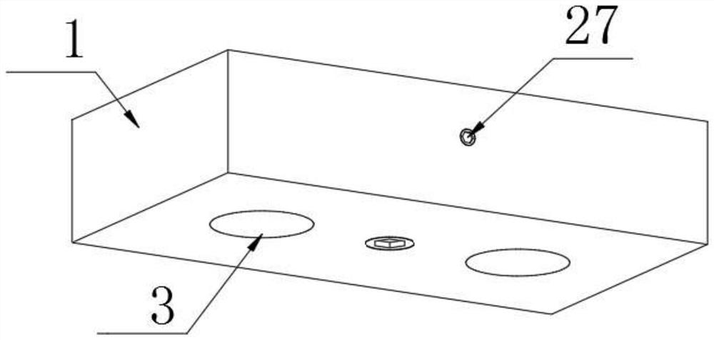
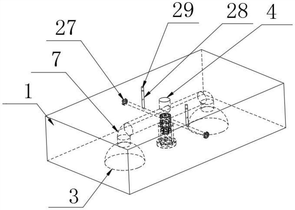
[0038]Embodiment 1, a mold with good injection molding effect, including an upper mold 1 and a lower mold 2, the opposite sides of the upper mold 1 and the lower mold 2 are provided with an injection cavity 3, and also includes the above-mentioned anti-overflow for the injection mold Device 30, the top of the upper mold 1 is provided with a main flow channel 4, the top of the main flow channel 4 is set as an input end 5, the bottom end of the main flow channel 4 is set as an output end 6, and the bottom of the main flow channel 4 is provided with an auxiliary The runner 7 communicates with the secondary runner 7. The secondary runner 7 is arranged on the top of the injection cavity 3 and communicates with the injection cavity 3. The inner walls of the main channel 4 and the secondary runner 7 are inlaid with heating coils 8 , the overflow prevention device 30 for the injection mold is arranged inside the upper mold 1 .

[0039] When in use, the upper mold 1 is driven downward ...

Embodiment 2

[0040] Example 2, such as Figure 1-5 and Figure 9 As shown, the inside of the upper mold 1 is located at the bottom of the secondary channel 7 and is provided with a flow control mechanism that controls the opening size of the output end 6 of the main channel 4. The flow control mechanism is connected to the heating coil 8 on the inner wall of the secondary channel 7, thereby passing The heat of the secondary channel 7 causes the flow control mechanism to expand with heat and contract with cold, and then adjust the opening size of the output end 6 of the main channel 4 to adjust the flow rate of the material entering the secondary channel 7 through the main channel 4, thereby adjusting the flow rate of the material in the secondary channel. 7 The internal flow rate, when the temperature is high, the intersecting part of the flow control mechanism and the main channel 4 is smaller, so that the output end 6 of the main channel 4 has a larger opening, and the material flows fas...

Embodiment 3

[0041] Example 3, such as Figure 2-4 and Figure 6-11 As shown, the flow control mechanism includes a first accommodating chamber 9 and a second accommodating chamber 10, the first accommodating chamber 9 is arranged at the bottom of the second accommodating chamber 10, the first accommodating chamber 9 and the second accommodating chamber Support rods 11 are fixedly connected between the chambers 10, a partition 12 is provided on the top of the first storage chamber 9, and a through groove 13 is provided on the partition 12, and a port 14 is provided on the first storage cavity 9. The top of the accommodation chamber 9 is provided with a sealing cloth 15, the sealing cloth 15 is made of rubber material, the sealing cloth 15 is arranged at the port 14, and a support plate 16 is arranged between the sealing cloth 15 and the partition plate 12, and the support plate 16 and The inner wall of the first storage chamber 9 is fixedly connected, and the center of the sealing cloth 1...


PUM


Abstract

The invention discloses a mold with a good injection molding effect and an anti-overflow device for the injection mold. The anti-overflow device for the injection mold comprises an upper mold body, a main runner is arranged at the top end in the upper mold body, the bottom of the main runner communicates with an auxiliary runner, a first accommodating cavity is formed in the position, located at the bottom of the auxiliary runner, in the upper mold body, and the anti-overflow device comprises a liquid storage unit, a rotating unit and a control unit, wherein the rotation of the rotating unit controls the opening and closing of the liquid storage unit; the control unit is used for controlling the rotation of the rotating unit; and the liquid storage unit is arranged in the inner wall of the main runner, the rotating unit is rotationally connected to the inner wall of the main runner, and the control unit is arranged in the first accommodating cavity. The rotation of the rotating unit is controlled through rotating magnetism of the control unit, and when the flow of the injection mold is reduced, accumulation of injection molding raw materials in the main runner is reduced, so that the injection molding raw materials enter the liquid storage unit through the rotating unit to facilitate secondary utilization to reduce waste.

Description

technical field [0001] The invention relates to the technical field of injection molds, in particular to a mold with good injection molding effect and an overflow prevention device for the injection mold. Background technique [0002] Plastic is a general term for daily necessities and industrial products processed from plastic as the main raw material. Injection mold is a tool that is matched with injection molding machine in the injection molding processing industry to give injection molded products a complete configuration and precise dimensions. Due to the variety of injection molding varieties and processing methods, the structures of injection molding machines and injection molded products are also complicated and simple, so the types and structures of injection molds are also diverse. [0003] Chinese invention patent CN105235151A discloses an injection mold, including an upper mold and a lower mold. Both the upper mold and the lower mold are cylindrical, and the upp...

Claims


Application Information

Patent Timeline
Patent Type & Authority Applications(China)
IPC IPC(8): B29C45/26
CPCB29C45/2669B29C2045/2671
Inventor 朱金娥王宏民陈毅
Owner 仙居县瑞亨吸塑厂
Why Eureka
Try Eureka