Clamping and conveying device

A clamping conveying and clamping block technology, which is applied in the direction of conveyor, transportation and packaging, etc., can solve the problems of poor stability and achieve the effect of efficient and stable conveying

Pending Publication Date: 2022-01-14
泰安华捷设备安装有限公司
View PDF0 Cites 0 Cited by
  • Summary
  • Abstract
  • Description
  • Claims
  • Application Information

AI Technical Summary

Problems solved by technology

In the process of retracting and unwinding the ropes such as steel wire ropes, the existing clamping and conveying devices for steel wire ropes and other ropes in the market have poor stability.

Method used


Image

  • Clamping and conveying device
  • Clamping and conveying device
  • Clamping and conveying device

Examples


Embodiment Construction

[0033] The principles and features of the present invention are described below in conjunction with the accompanying drawings, and the examples given are only used to explain the present invention, and are not intended to limit the scope of the present invention.

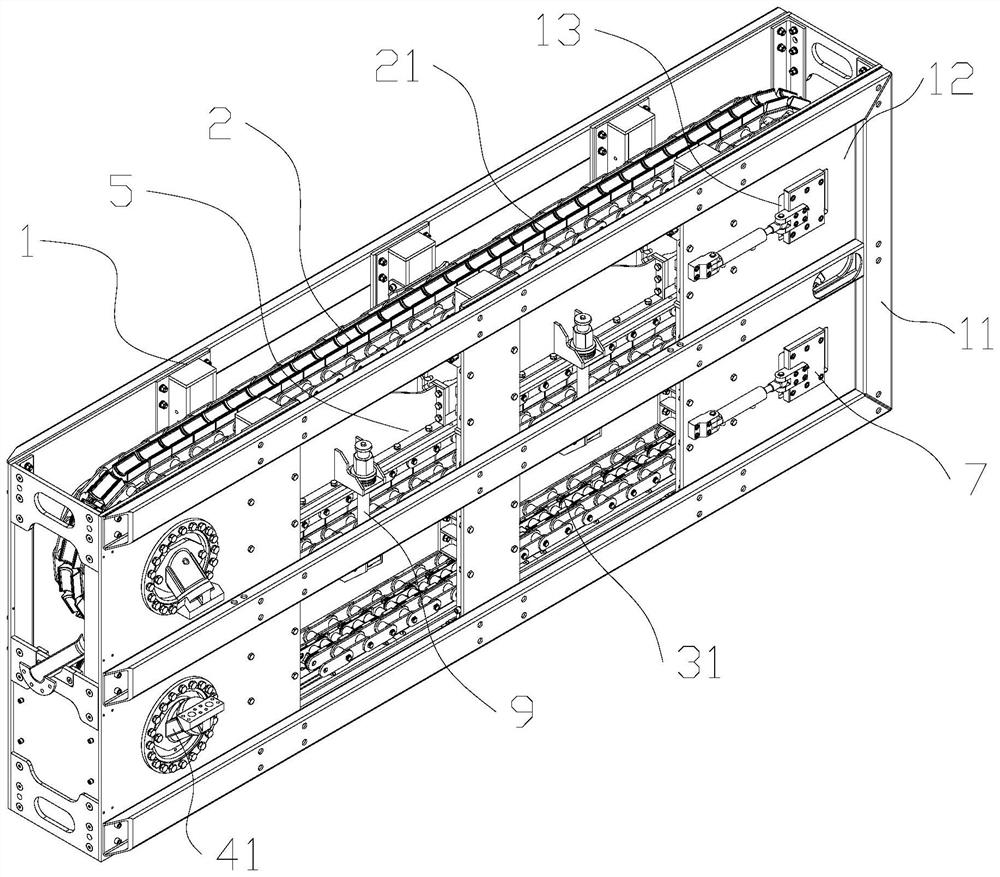
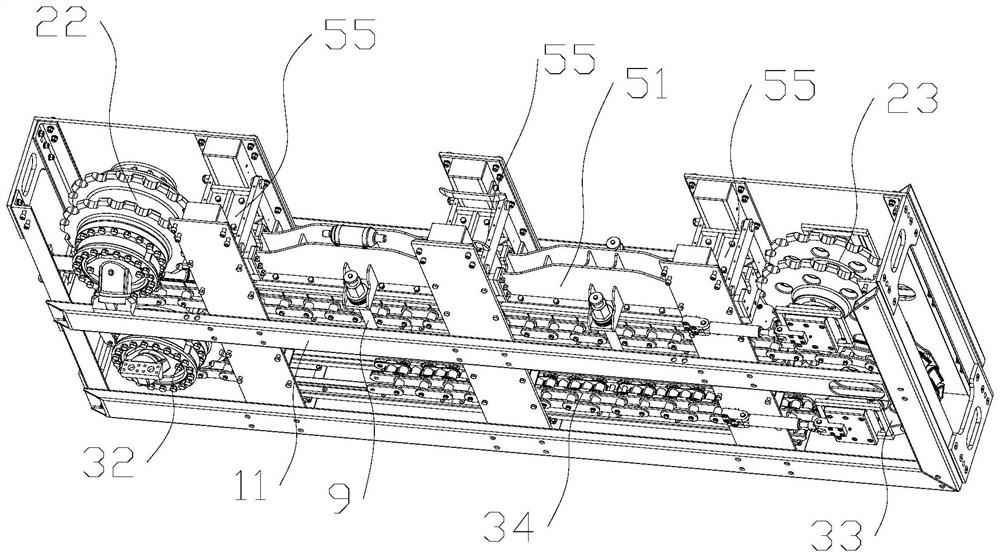
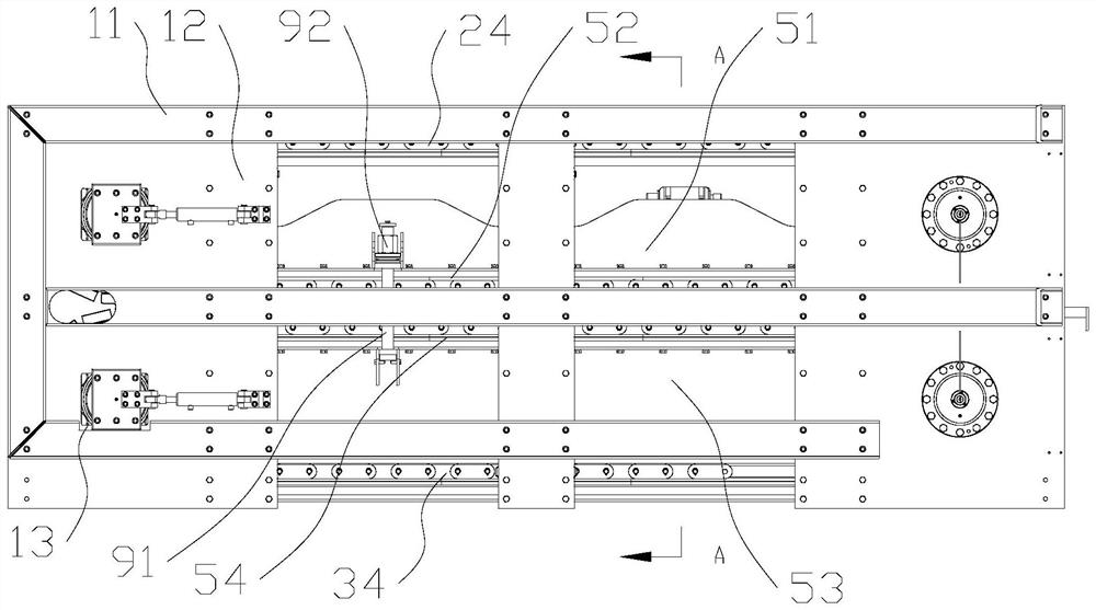
[0034] Such as Figure 1-Figure 4 As shown, a clamping and conveying device according to an embodiment of the present invention includes a bracket 1 , a chain conveying mechanism 2 , a clamping mechanism 5 and a sprocket tensioning mechanism 7 . The support 1 is used to install the chain conveying mechanism 2, the clamping mechanism 5 and the sprocket tensioning mechanism 7, and includes a frame 11 and a fixing plate 12 installed on the frame 11. The shape of the support 1 is a cuboid.

[0035] The chain conveying mechanism 2 includes an upper clamping transmission chain assembly 21 and a lower clamping transmission chain assembly 31 . The upper clamping transmission chain assembly 21 includes an upper driving spro...


PUM


Abstract

The invention discloses a clamping and conveying device. The clamping and conveying device comprises a support, a chain type conveying mechanism, a clamping mechanism and a chain wheel tensioning mechanism. The chain type conveying mechanism comprises an upper clamping transmission chain assembly and a lower clamping transmission chain assembly; and each of an upper clamping transmission chain and a lower clamping transmission chain comprises a first chain, a second chain and a clamping chain which is arranged between the first chain and the second chain, connected to the first chain and the second chain and used for clamping a rope body, and the upper clamping transmission chain and the lower clamping transmission chain are arranged up and down; and the clamping mechanism can drive the upper clamping transmission chain and the lower clamping transmission chain to clamp the rope body located between the upper clamping transmission chain and the lower clamping transmission chain, and the chain wheel tensioning mechanism can tension the upper clamping transmission chain and the lower clamping transmission chain. According to the clamping and conveying device, the rope body such as a steel wire rope can be efficiently and stably conveyed.

Description

technical field [0001] The invention relates to the clamping field of a wire rope receiving and releasing device, in particular to a clamping and conveying device, which is used in some steel wire rope replacement occasions such as ports, mines, cable cars, and power plants, as well as cable retraction occasions. Background technique [0002] In the prior art, the winding and unwinding of the steel wire rope mainly adopts winding type retracting and unwinding, and in the winding type traction process, the power is mainly provided by the winch, and the cylinder winding method is used. This winding traction structure is directly wound under the state of traction, which will cause tensile stress to reduce the tensile performance of the rope body after winding; in addition, the winding process will cause deformation inside and outside the section of the steel wire rope, extruding inside and stretching outside; and Forced clamping and winding will cause the steel wire ropes to be...

Claims


Application Information

Patent Timeline
Patent Type & Authority Applications(China)
IPC IPC(8): B65G17/30B65G17/12B65G23/44
CPCB65G17/30B65G17/12B65G23/44
Inventor 谢中秀
Owner 泰安华捷设备安装有限公司
Why Eureka
Try Eureka