Left-right reversing lock

A lock, left and right technology, applied in the field of locks, can solve the problems of long screw loss, inconvenient use, complex structure, etc., and achieve the effect of not easy to lose, convenient to use, accurate and reliable transmission

Active Publication Date: 2022-01-14
广东爱胜德五金制品有限公司
View PDF2 Cites 0 Cited by
  • Summary
  • Abstract
  • Description
  • Claims
  • Application Information

AI Technical Summary

Problems solved by technology

[0002] In the current lock installation, in the common lock structure, it is common to install on the door and window by screw connection. Due to the need for screw connection installation, there is usually a mounting block with a nut function on one side, which leads to the need to correspond to the left and right directions when installing the lock. ; Due to the fixed transmission structure of the lock cylinder and the transmission point and the fixed setting of the installation block, in the conventional structure, if it is necessary to reversing the installation in the left and right directions, it is necessary to rotate the lockset by 180° horizontally and 180° vertically. It can be installed, and this kind of installation will cause the transmission point to be different from the original one. When the handle is installed, it will be placed horizontally instead of vertically (that is, turned 90°), which is very inconvenient to use.
[0003] In the existing design, there is also a detachable mounting block as a reversing mounting block, but this type of reversing mounting block usually requires long screws to cooperate, the structure is complicated, and the long screws are easy to be lost during transportation or normal use. lost, inconvenient

Method used


Image

  • Left-right reversing lock
  • Left-right reversing lock
  • Left-right reversing lock

Examples


Embodiment Construction

[0026] The following will clearly and completely describe the technical solutions in the embodiments of the present invention with reference to the accompanying drawings in the embodiments of the present invention. Obviously, the described embodiments are only some, not all, embodiments of the present invention. Based on the embodiments of the present invention, all other embodiments obtained by persons of ordinary skill in the art without making creative efforts belong to the protection scope of the present invention.

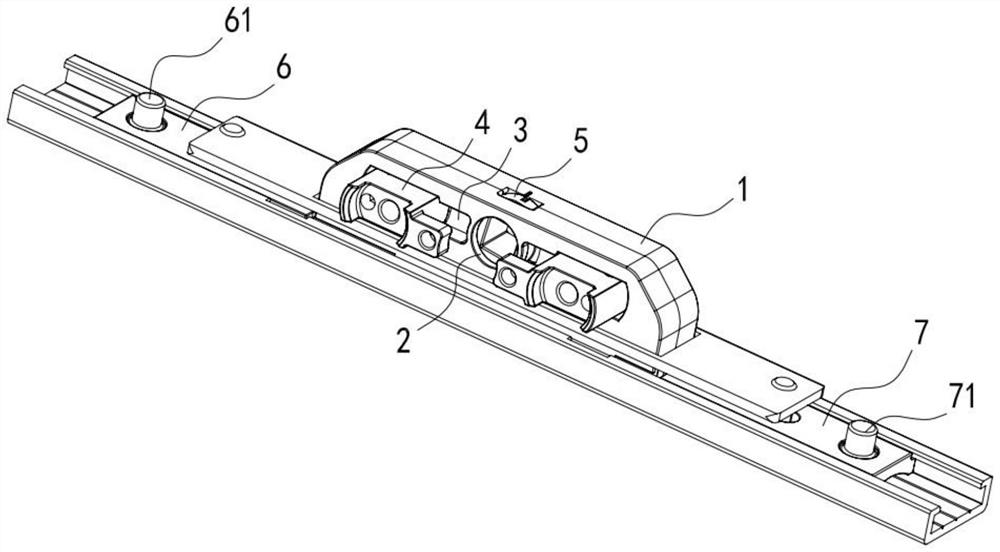
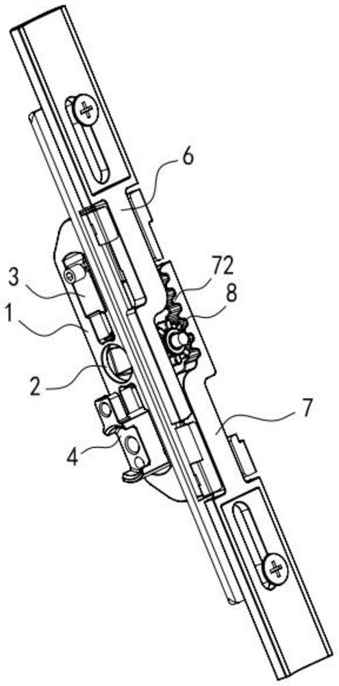
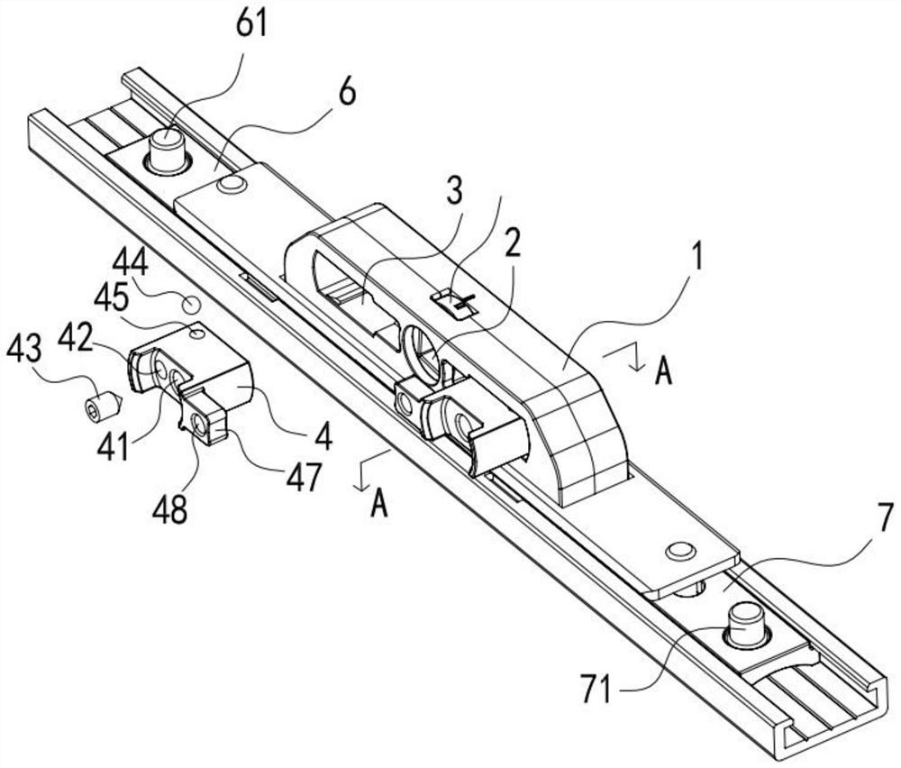
[0027] see figure 1 , 2 , the present invention provides a technical solution:

[0028] Left and right reversible locks include a lock body 1, a handle hole 2 is opened in the center of the lock body 1, a lock cylinder 5 arranged in the handle hole 2, a lock transmission structure that cooperates with the lock cylinder 5, and both sides of the handle hole 2 A reversing installation area 3 that runs through the lock body 1 is set up, and also includes two rev...


PUM


Abstract

The invention relates to the field of locks, and particularly discloses a left-right reversing lock. The left-right reversing lock comprises a reversing installation block, the reversing installation block and the reversing installation area are detachably installed, the reversing installation block is provided with a lock installation hole used for installing the lock, the reversing installation block is provided with a reversing installation hole, and an installation screw matched with the reversing installation hole in a threaded mode and an installation ball matched with the installation screw are arranged in the reversing installation hole; and the reversing installation block is provided with a locking hole, the locking hole is communicated with the reversing installation hole, the installation ball is driven by the installation screw to move in the locking hole, the part, penetrating out of the locking hole, of the installation ball abuts against the inner wall of the reversing installation area, a lock transmission structure comprises a first transmission piece and a second transmission piece, the first transmission piece is in meshing transmission with a lock cylinder gear, and the second transmission piece is in gear meshing transmission with the first transmission piece. By means of the left-right reversing lock, free reversing can be achieved, the transmission point and an installation position are not changed after reversing, and use is greatly facilitated.

Description

technical field [0001] The invention relates to the field of locks, in particular to a lock with a left-right reversing installation structure. Background technique [0002] In the current lock installation, in the common lock structure, it is common to install on the door and window by screw connection. Due to the need for screw connection installation, there is usually a mounting block with a nut function on one side, which leads to the need to correspond to the left and right directions when installing the lock. ; Due to the fixed transmission structure of the lock cylinder and the transmission point and the fixed setting of the installation block, in the conventional structure, if it is necessary to reversing the installation in the left and right directions, it is necessary to rotate the lockset by 180° horizontally and 180° vertically. It can be installed, and this installation will cause the transmission point to be different from the original one. When the handle is ...

Claims


Application Information

Patent Timeline
Patent Type & Authority Applications(China)
IPC IPC(8): E05B63/04E05B3/00E05B15/00
CPCE05B63/04E05B3/00E05B15/00
Inventor 郑坤柳奕斌
Owner 广东爱胜德五金制品有限公司
Why Eureka
Try Eureka