
Valve stress releasing method

A stress release and stress technology, applied in the direction of measuring devices, instruments, optical devices, etc., can solve problems such as poor pertinence, long time-consuming valve stress, uneven force on equipment, etc., to achieve rapid stress concentration, improve maintenance efficiency, and maintain The effect of force

Pending Publication Date: 2022-01-14
北京市南水北调环线管理处
View PDF13 Cites 0 Cited by
  • Summary
  • Abstract
  • Description
  • Claims
  • Application Information

AI Technical Summary

Problems solved by technology

[0004] Therefore, the technical problem to be solved by the present invention is to overcome the defects in the prior art that the valve stress takes a long time, is poorly targeted, and easily causes uneven force on the equipment, thereby providing a method for releasing the valve stress

Method used


Image

  • Valve stress releasing method

Examples


Embodiment 1

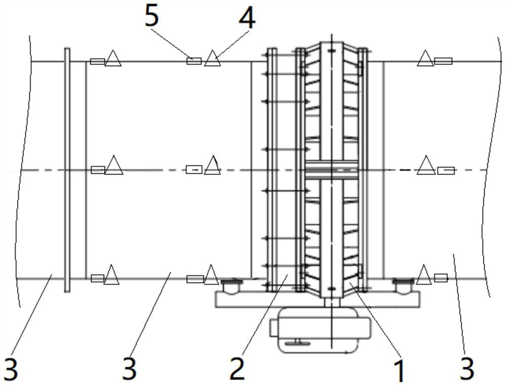
[0033] The delivery pipeline provided in this embodiment, such as figure 1 As shown, it includes: a valve 1, a force transmission expansion joint 2 and a plurality of pipe sections 3; one end of the valve 1 is connected to the force transmission expansion joint 2, and the other end is connected to a pipe section 3. A pipe section 3 is connected to the interface of the force expansion joint 2 away from the end of the valve 1; the other end of the pipe section 3 connected to the force transmission expansion joint 2 is connected to a plurality of pipe sections 3 in sequence, and the pipe section 3 connected to the valve 1 A plurality of pipe sections 3 are sequentially connected at the other end of the pipe section 3 .

Embodiment 2

[0035] The method for releasing the stress of the valve 1 provided in this embodiment includes the following steps:

[0036] S1: Detect the concentricity and coaxiality of the conveying pipeline, analyze the deformation trend of the conveying pipeline, and use the area with the largest deformation tendency as the initial stress release operation area.

[0037] The specific steps of detection and analysis of concentricity and coaxiality are as follows:

[0038] a. The conveying pipeline is arranged with four measuring lines in the axial direction, and the four measuring lines are all located on the outer circumference of the conveying pipeline, and the azimuth angle between two adjacent measuring lines is 90°; on the same measuring line, the conveying pipeline There are at least two measuring points 4 on each part.

[0039] b. Take the leftmost pipe section 3 of the conveying pipeline as the starting end, and take the axis of the pipe section 3 as the reference axis; use the l...


PUM


Abstract

The invention provides a valve stress releasing method. The valve stress releasing method comprises the following steps of detecting the concentricity and the coaxiality of a conveying pipeline, analyzing the deformation trend of the conveying pipeline, and taking the area with the largest deformation trend as a stress initial releasing operation area, monitoring the stress change of the conveying pipeline, analyzing according to a strain monitoring value, and taking a part with an increased strain value as a stress initial releasing operation part, and sequentially operating the force transmission expansion joints at the stress initial releasing operation part and the stress initial releasing operation area to complete stress releasing. According to the releasing method, targeted stress releasing can be conducted on the valve according to the actual working condition, so that stress concentration of the conveying pipeline can be rapidly eliminated, and uniform stress is kept; according to the releasing method, the part with large stress concentration can be preferentially and rapidly released, the overall releasing time of the stress is shortened, and the maintenance efficiency of the valve is improved.

Description

technical field [0001] The invention relates to the technical field of valve equipment maintenance, in particular to a valve stress releasing method. Background technique [0002] At present, the stress release of the valve equipment is to loosen or tighten the force transmission nut of the force transmission expansion joint through a conventional wrench tool, check the force condition of the bolt, and complete the release of the valve stress. [0003] The above-mentioned stress release method takes a long time and easily causes uneven stress on the equipment, which affects the later operation of the valve and reduces the service efficiency and service life of the valve. Contents of the invention [0004] Therefore, the technical problem to be solved by the present invention is to overcome the defects in the prior art that the valve stress takes a long time, is poorly targeted, and easily causes uneven force on the equipment, so as to provide a method for releasing the val...

Claims


Application Information

Patent Timeline
Patent Type & Authority Applications(China)
IPC IPC(8): G01B11/16G01B11/27
CPCG01B11/16G01B11/27
Inventor 李博展王新春李建利罗强杨金凤刘洋张秀微李娜董龑蛟李伟张鑫
Owner 北京市南水北调环线管理处
Learn More