Optical module and head-mounted display device

A technology for optical modules and displays, applied in optics, optical components, instruments, etc., can solve the problems of inconvenience to wear, high pressure for display pixel compensation, and large size of head-mounted display devices.

Pending Publication Date: 2022-01-14
GOERTEK OPTICAL TECH CO LTD
View PDF7 Cites 2 Cited by
  • Summary
  • Abstract
  • Description
  • Claims
  • Application Information

AI Technical Summary

Problems solved by technology

In related technologies, the enlarged image requires a sufficiently long optical path, so the total optical length of the optical system is longer, resulting in a larger volume of the head-mounted display device, which i

Method used


Image

  • Optical module and head-mounted display device
  • Optical module and head-mounted display device
  • Optical module and head-mounted display device

Examples


Embodiment Construction

[0032] The following will clearly and completely describe the technical solutions in the embodiments of the present invention with reference to the accompanying drawings in the embodiments of the present invention. Obviously, the described embodiments are only part of the embodiments of the present invention, not all of them. Based on the embodiments of the present invention, all other embodiments obtained by persons of ordinary skill in the art without creative efforts fall within the protection scope of the present invention.

[0033] It should be noted that all directional indications (such as up, down, left, right, front, back...) in the embodiments of the present invention are only used to explain the relationship between the components in a certain posture (as shown in the accompanying drawings). Relative positional relationship, movement conditions, etc., if the specific posture changes, the directional indication will also change accordingly.

[0034] In the present in...


PUM


Abstract

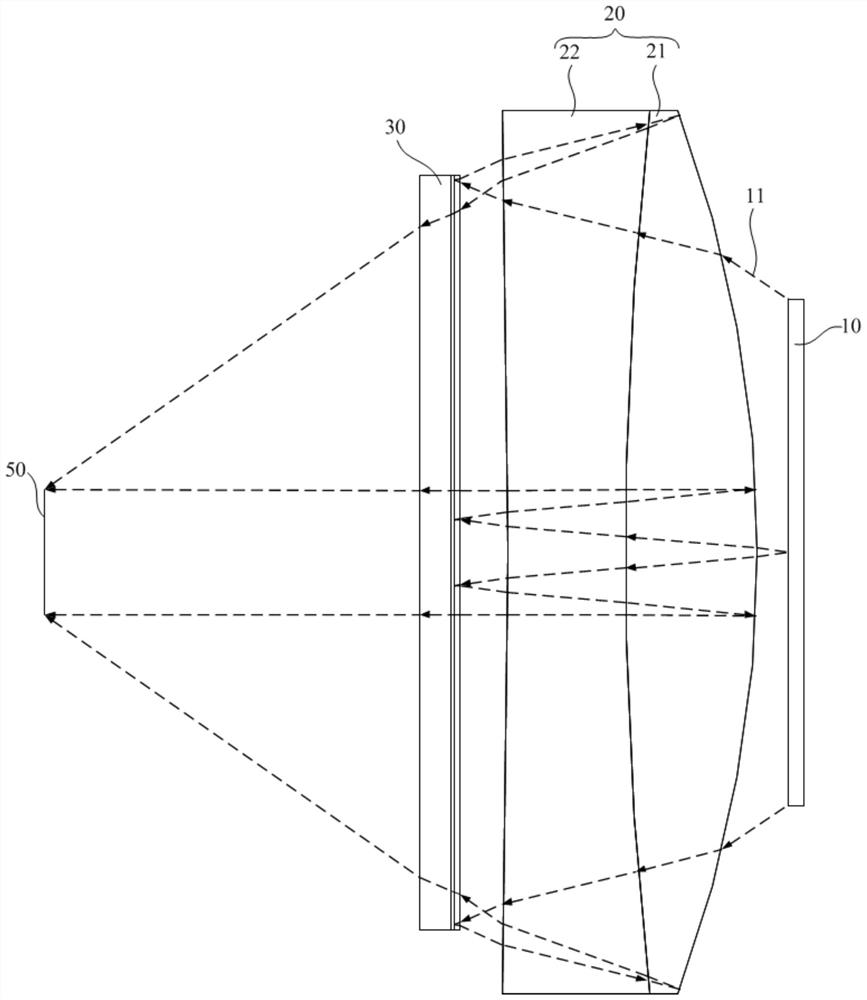
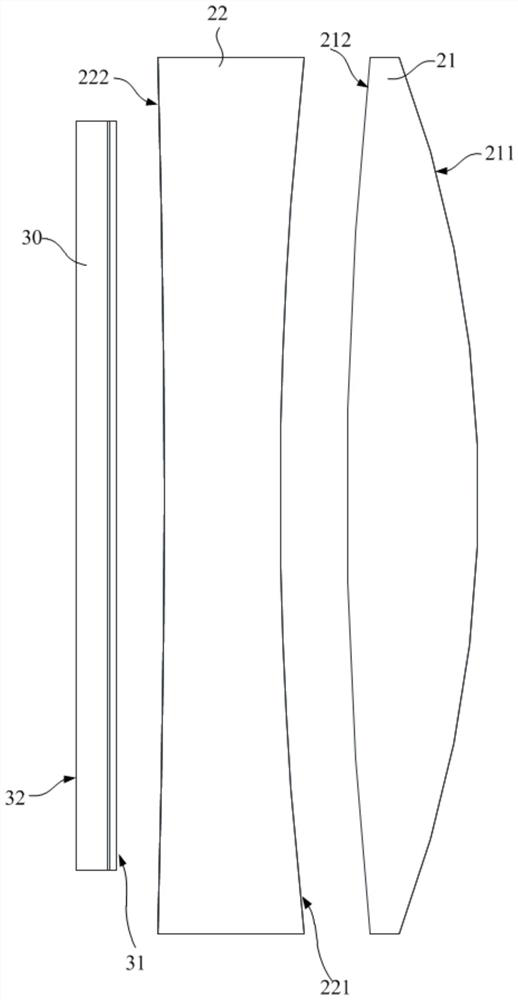
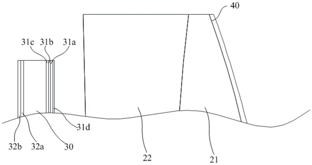
The invention discloses an optical module and a head-mounted display device. The optical module comprises a display which emits light for imaging display. A bonding lens is arranged in the light emitting direction of the display and comprises a first lens and a second lens which are sequentially arranged along the direction away from the display, the Abbe number of the material of the first lens is different from the Abbe number of the material of the second lens, a light splitting element is arranged on the first surface, and a flat plate element is arranged on the side, away from the first lens, of the second lens. The flat plate element is provided with a fifth surface facing the second lens, and a quarter-wave plate and a polarization reflection film are sequentially attached to the fifth surface in the direction away from the second lens. According to the technical scheme, the size of the head-mounted display device can be reduced by reducing the total optical length of the optical system, a user can wear the head-mounted display device conveniently, meanwhile, it is guaranteed that the chromatic aberration value of the imaged image is low, and the compensation pressure of imaging software on display pixels of the image in the later period is reduced.

Description

technical field [0001] The invention relates to the technical field of optical display, in particular to an optical module and a head-mounted display device using the optical module. Background technique [0002] With the development and upgrading of advanced optical design and processing technology, display technology and processor, the forms and types of virtual reality (VR) products emerge in endlessly, and its application fields are becoming more and more extensive. The main working principle of virtual reality products is that after the image displayed on the display is transmitted and magnified by optical lenses, the image is then received by the human eye, and what the human eye observes is a magnified virtual image. In related technologies, the enlarged image requires a sufficiently long optical path, so the total optical length of the optical system is longer, resulting in a larger volume of the head-mounted display device, which is not convenient for users to wear,...

Claims


Application Information

Patent Timeline
IPC IPC(8): G02B27/01
CPCG02B27/0172
Inventor 孙琦
Owner GOERTEK OPTICAL TECH CO LTD
Why Eureka
Try Eureka