Retarder, liquid crystal display element, and liquid crystal projector

a liquid crystal display element and display element technology, applied in the field of retarders, liquid crystal display elements, and liquid crystal projectors, can solve the problems of difficult to obtain space, inherently limited distance between the first polarizer and the liquid crystal element, and further difficult to obtain the desired image quality with the optical design, etc., to achieve excellent liquid crystal projectors, improve light transmission efficiency, and high contrast ratio

Inactive Publication Date: 2007-06-28
SONY CORP
View PDF1 Cites 3 Cited by
  • Summary
  • Abstract
  • Description
  • Claims
  • Application Information

AI Technical Summary

Benefits of technology

[0013] Even when the spaces in which the optical anisotropic elements tilted at an angle are disposed can be obtained, the distance between the illumination optical system and the liquid crystal element or the distance between the liquid crystal element and the projection lens becomes long. Accordingly, the optical design may have to be changed significantly. In particular, if an optical anisotropic element tilted at an angle is disposed between the second polarizer and the liquid crystal element, the optical length between the liquid crystal element and the projection lens becomes long. Accordingly, the back focus of the projection lens needs to be increased. If the back focus of the projection lens is long, it becomes further difficult to obtain the desired image quality with the optical design. Furthermore, the diameter of the projection lens is increased, and therefore, the manufacturing cost of the projection lens is also increased and the size or the weight of the liquid crystal projector is increased.
[0014] Accordingly, the present invention provides a retarder capable of increasing the light transmission efficiency while maintaining a high contrast ratio of a transmissive liquid crystal display element and preventing the size of a projector using the liquid crystal display element from increasing. Furthermore, the present invention provides a compact liquid crystal display element and a compact projector using this retarder that can display a high-resolution image.
[0020] As noted above, according to the retarder of the embodiment of the present invention, the retarder can have a structure that is thin in a direction of the optical axis of an incident light beam provided with retardation. Therefore, the liquid crystal display element including the retarder can maintain the compact size thereof while maintaining a high contrast ratio and improving the light transmission efficiency. As a result, a liquid crystal display element that can maintain the compact size thereof and display a high-resolution image and an excellent liquid crystal projector including the liquid crystal display element can be achieved.

Problems solved by technology

However, for liquid crystal projectors, the distances between the first polarizer and the liquid crystal element and between the second polarizer and the liquid crystal element are inherently limited.
Thus, it is difficult to obtain spaces in which the optical anisotropic elements tilted at an angle are disposed.
If the back focus of the projection lens is long, it becomes further difficult to obtain the desired image quality with the optical design.
Furthermore, the diameter of the projection lens is increased, and therefore, the manufacturing cost of the projection lens is also increased and the size or the weight of the liquid crystal projector is increased.

Method used


Image

  • Retarder, liquid crystal display element, and liquid crystal projector
  • Retarder, liquid crystal display element, and liquid crystal projector
  • Retarder, liquid crystal display element, and liquid crystal projector

Examples


first exemplary embodiment

Retarder

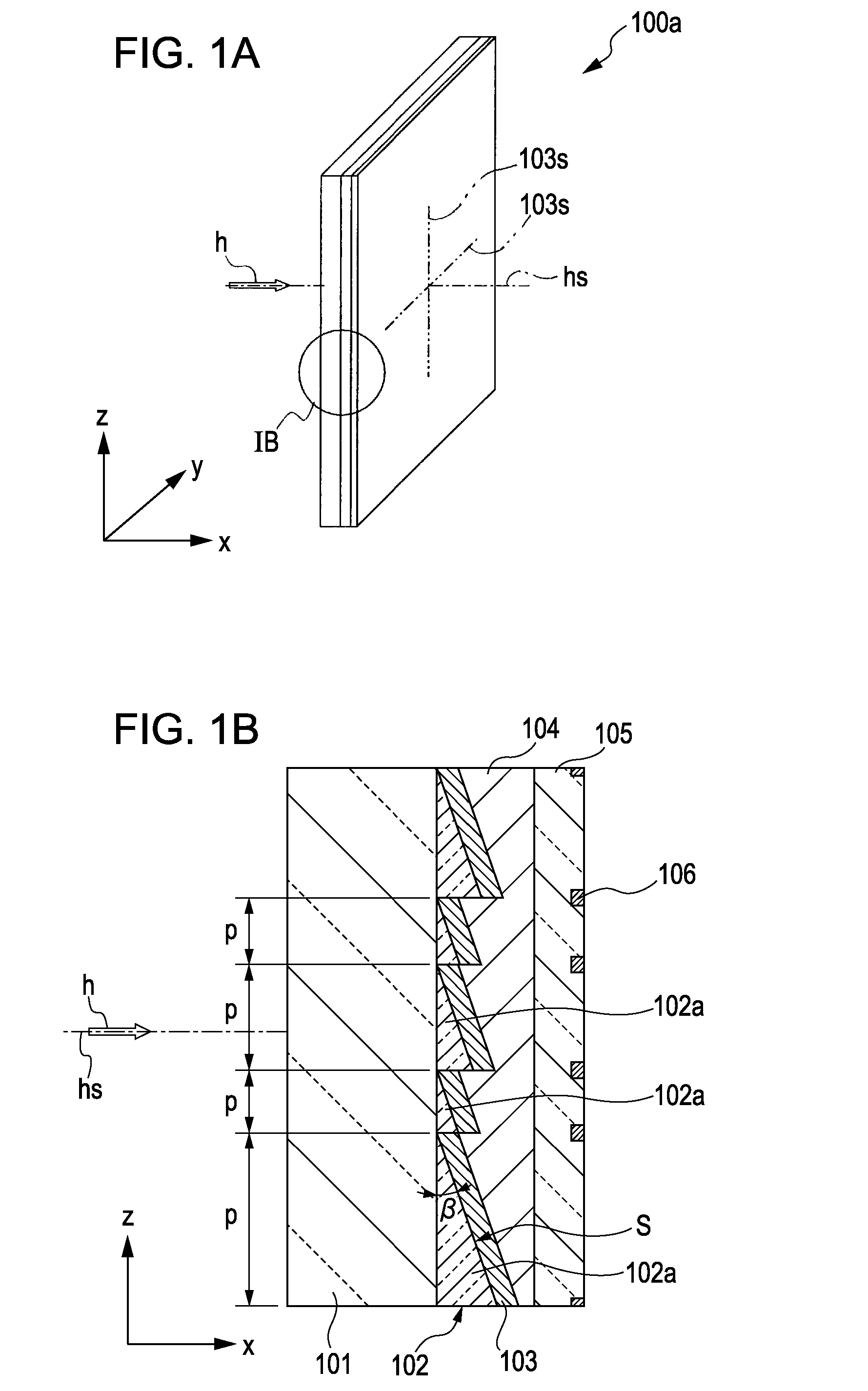
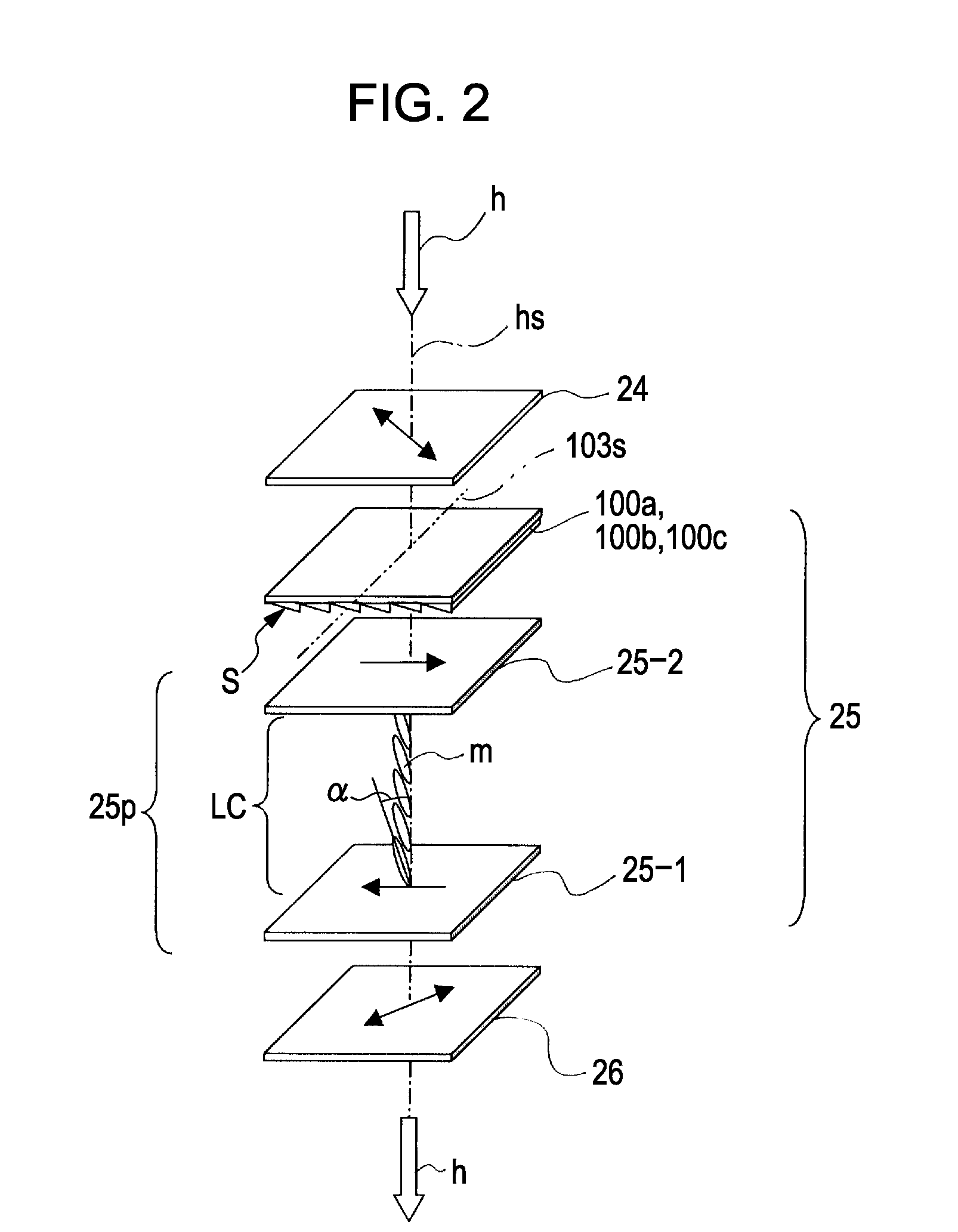
[0039]FIG. 1A is a perspective view of a retarder according to a first exemplary embodiment of the present invention. FIG. 1B is an enlarged cross-sectional view of a section denoted by IB in the perspective view of FIG. 1A. A retarder 100a shown in FIGS. 1A and 1B is incorporated in a liquid crystal element which will be described below with reference to FIGS. 2 and 3 and serves as part of the liquid crystal element.

[0040] The retarder 100a includes a transparent support substrate 101, a prism layer 102 disposed on one of the main surfaces of the transparent support substrate 101, an optical anisotropic medium layer 103 disposed on the prism layer 102, a planarizing layer 104 for covering the optical anisotropic medium layer 103, and a cover glass 105.

[0041] The transparent support substrate 101 is formed from, for example, quartz. The transparent support substrate 101 has a thickness that can support the prism layer 102 disposed thereon (e.g., about 1 mm).

[0042] The p...

second exemplary embodiment

Retarder

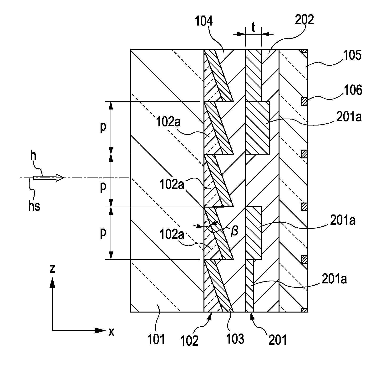
[0072]FIG. 5A is a perspective view of a retarder according to a second exemplary embodiment of the present invention. FIG. 5B is an enlarged cross-sectional view of a section denoted by VB in the perspective view of FIG. 5A. A retarder 100b shown in FIGS. 5A and 5B is different from the retarder of the first exemplary embodiment in that the retarder 100b has a different structure of the prism layer 102 and further includes a random phase shifter layer 201 and a planarizing layer 202 between the planarizing layer 104 and the cover glass 105. The other structures of the second exemplary embodiment are similar to those of the first exemplary embodiment.

[0073] That is, the prism layer 102 includes a plurality of the microprisms 102a having the same cross section at the same pitch. Like the retarder 100a of the first exemplary embodiment shown in FIG. 1, the microprisms 102a is formed from, for example, quartz. The microprisms 102a have the same prism apex angle β. Each of th...

third exemplary embodiment

Retarder

[0079]FIG. 6A is a perspective view of a retarder according to a third exemplary embodiment of the present invention. FIG. 6B is an enlarged cross-sectional view of a section denoted by VIB in the perspective view of FIG. 6A. A retarder 100c shown in FIGS. 6A and 6B is different from the retarder of the first exemplary embodiment in that the retarder 100c has a different structure of the prism layer 102 and further includes a random phase shifter layer 201 between the transparent support substrate 101 and the prism layer 102.

[0080] That is, the prism layer 102 has a structure similar to that described in FIG. 5. The microprisms 102a each having the same cross section are arranged in multiple lines at the same pitch.

[0081] A random phase shifter layer 201 has a structure similar to that of the random phase shifter layer 201 described in FIG. 5. A plurality of phase shifters 201a are arranged on the transparent support substrate 101 at the same pitch as that of the micropr...


PUM


Abstract

A retarder includes a transparent support substrate, a prism layer including a plurality of microprisms arranged on one of main surfaces of the transparent support substrate, where each of the microprisms has a sloped prism face formed at the same slope angle with respect to the one main surface in the same direction, an optical anisotropic medium layer disposed on the sloped prism face so that an optic axis of the optical anisotropic medium layer is directed in one of a direction of the maximum sloped prism face of the microprisms and a direction perpendicular to the direction of the maximum sloped prism face, and a planarizing layer disposed on the transparent support substrate so as to embed the optical anisotropic medium layer therein. The planarizing layer is formed from a material having an index of refraction that is substantially the same as that of the microprisms.

Description

CROSS REFERENCES TO RELATED APPLICATIONS [0001] The present invention contains subject matter related to Japanese Patent Application JP 2005-341396 filed in the Japanese Patent Office on Nov. 28, 2005, the entire contents of which are incorporated herein by reference. BACKGROUND OF THE INVENTION [0002] 1. Field of the Invention [0003] The present invention generally relates to a retarder, a liquid crystal display element, and a liquid crystal projector and, in particular, to a liquid crystal projector that has a compact body and that provides low light loss, high contrast, and high response speed by including a display element using an electric-field-controlled birefringence mode liquid crystal panel. [0004] 2. Description of the Related Art [0005] Liquid crystal projectors are known that modulate light output from a light source using, for example, a transmissive liquid crystal display element so as to form light of an image and that project the light of an image onto, for example,...

Claims


Application Information

Patent Timeline
IPC IPC(8): G02F1/1335
CPCG02B5/045G02B5/3083G02F1/13363G02F1/1337G02F2413/02G02F2413/07G02F2413/09G02F2413/10H04N9/3167G02F1/133631
Inventor WATANABE, SHINYA
Owner SONY CORP
Why Eureka
Try Eureka