Infrared confocal lens

An infrared confocal lens technology, applied in the field of infrared confocal lens, achieves the effects of smooth light, miniaturization, and low manufacturing cost

Active Publication Date: 2022-01-28
JIANGXI LIANCHUANG ELECTRONICS CO LTD
View PDF7 Cites 3 Cited by
  • Summary
  • Abstract
  • Description
  • Claims
  • Application Information

AI Technical Summary

Problems solved by technology

However, it is difficult for existing lenses on the market to meet the above requirements at the same time. Therefore, it is urgent to design a lens with large light transmission, clear imaging, athermalization, and confocal day and night to better meet the needs of vehicle systems.

Method used


Image

  • Infrared confocal lens
  • Infrared confocal lens
  • Infrared confocal lens

Examples


no. 1 example

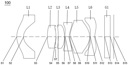
[0069] see figure 1 , is a schematic diagram of the structure of the infrared confocal lens 100 provided in the first embodiment of the present invention. The infrared confocal lens 100 includes in sequence from the object side to the imaging surface along the optical axis: a first lens L1, a second lens L2, and a stop ST , the third lens L3, the fourth lens L4, the fifth lens L5, the sixth lens L6, and the filter G1.

[0070] The first lens L1 has negative refractive power, the object side S1 of the first lens is a convex surface, and the image side S2 of the first lens is a concave surface;

[0071] The second lens L2 has a positive refractive power, and both the object side S3 and the image side S4 of the second lens are convex;

[0072] The third lens L3 has positive refractive power, the object side S5 of the third lens is concave, and the image side S6 of the third lens is convex;

[0073] The fourth lens L4 has negative refractive power, the object side S7 of the four...

no. 2 example

[0087] see Figure 4 , shows a schematic diagram of the structure of the infrared confocal lens 200 provided in this embodiment, the infrared confocal lens 200 in this embodiment and the infrared confocal lens 100 in the first embodiment have roughly the same surface concave and convex, different The difference is that the object side S5 of the third lens L3 is convex at the near optical axis, and there are differences in the parameters such as the radius of curvature and thickness of each lens. Specifically, relevant parameters of each lens of the infrared confocal lens 200 in this embodiment are shown in Table 3.

[0088] table 3

[0089]

[0090] The relevant parameters of the aspheric lens of the infrared confocal lens 200 in this embodiment are shown in Table 4.

[0091] Table 4

[0092]

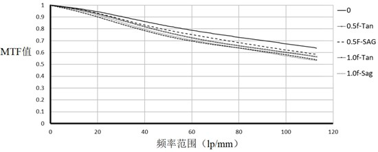
[0093] The MTF curves of the infrared confocal lens 200 provided in this embodiment under the spectral conditions of 435nm-650nm (visible light) and 900nm-1100nm (infrared ligh...

no. 3 example

[0095] see Figure 7 , shows a schematic diagram of the structure of the infrared confocal lens 300 provided in this embodiment, the infrared confocal lens 300 in the present embodiment and the infrared confocal lens 100 in the first embodiment have roughly the same concave-convex surface shape, different The difference is that the object side S5 of the third lens L3 is convex, and the object side S7 of the fourth lens L4 is concave at the near optical axis, and there are differences in parameters such as the radius of curvature and thickness of each lens. Specifically, relevant parameters of each lens of the infrared confocal lens 300 in this embodiment are shown in Table 5.

[0096] table 5

[0097]

[0098]The relevant parameters of the aspheric lens of the infrared confocal lens 300 in this embodiment are shown in Table 6.

[0099] Table 6

[0100]

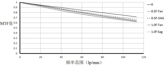
[0101] The vertical axis chromatic aberration and axial chromatic aberration of the infrared confocal lens 300 prov...


PUM


Abstract

The invention discloses an infrared confocal lens which sequentially comprises a first lens, a second lens, a diaphragm, a third lens, a fourth lens, a fifth lens and a sixth lens from an object side to an imaging surface along an optical axis. The first lens has negative focal power, the object side surface is a convex surface, and the image side surface is a concave surface; the second lens has positive focal power, and the object side surface and the image side surface of the second lens are convex surfaces; the infrared confocal lens further comprises a diaphragm; the third lens has positive focal power, and the image side surface of the third lens is a convex surface; the fourth lens has negative focal power, and the image side surface of the fourth lens is a concave surface near the optical axis; the fifth lens has positive focal power, and the object side surface and the image side surface of the fifth lens are convex surfaces; and the sixth lens has negative focal power, the object side surface of the sixth lens is a convex surface near the optical axis, the image side surface of the sixth lens is a concave surface near the optical axis, and the object side surface and the image side surface of the sixth lens are respectively provided with at least one inflection point. The infrared confocal lens has the advantages of high light flux, high definition, athermalization and day and night confocal property.

Description

technical field [0001] The invention relates to the technical field of imaging lenses, in particular to an infrared confocal lens. Background technique [0002] In recent years, with the vigorous development of the automobile industry, automation and in-vehicle monitoring and sensing systems have begun to develop rapidly, and the vehicle lens, as a key component of the automatic driving assistance system, has also ushered in rapid development. The imaging quality of the vehicle lens And reliability are increasingly considered by car manufacturers. [0003] Due to the complex and changeable application environment of automobiles and high safety performance requirements, the reliability requirements for camera lenses installed in in-vehicle driver assistance systems will be higher than ordinary optical lenses. To ensure high-quality image output under different lighting conditions during the day and night, it also needs to have strong environmental adaptability to ensure that...

Claims


Application Information

Patent Timeline
Patent Type & Authority Applications(China)
IPC IPC(8): G02B13/00G02B13/18G02B13/14
CPCG02B13/0045G02B13/18G02B13/008
Inventor 凌兵兵鲍宇旻王克民
Owner JIANGXI LIANCHUANG ELECTRONICS CO LTD
Why Eureka
Try Eureka