A floating grooving machine

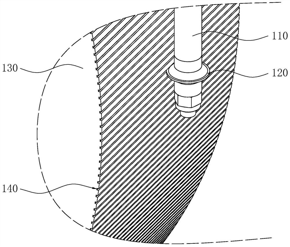
A grooved, floating technology, applied in metal processing equipment, milling machine equipment, manufacturing tools, etc., can solve the problems of deepening the depth of the mica groove 140, reducing the commutator 130, deformation of the outer peripheral surface, etc., so as to reduce the runout. The probability of improving the commutation performance and the effect of improving the machining accuracy

Active Publication Date: 2022-07-26
JINAN TAICHAN TECH CO LTD
View PDF15 Cites 0 Cited by
  • Summary
  • Abstract
  • Description
  • Claims
  • Application Information

AI Technical Summary

Problems solved by technology

[0004] In view of the related technologies mentioned above, the inventor believes that during the wear process of the commutator 130, not only the outer diameter of the commutator 130 will be reduced, but also the outer peripheral surface of the commutator 130 will be deformed, so that the mica groove 140 It is no longer straight, but is irregularly wave-shaped and arranged on the outer peripheral surface of the commutator 130; Can widen the width of mica groove 140, even make two adjacent mica grooves 140 connect, when two adjacent mica grooves 140 connect, commutator 130 just can be scrapped

Method used


Image

  • A floating grooving machine
  • A floating grooving machine
  • A floating grooving machine

Examples


Embodiment Construction

[0042] Attached to the following Figure 2-5 This application will be described in further detail.

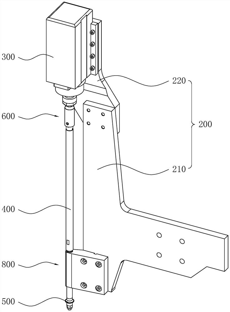
[0043] The embodiment of the present application proposes a floating type notching machine. refer to figure 2 , the floating slotting machine includes a frame 200 , a drive motor 300 , a main shaft 400 , a milling cutter 500 , a floating connection mechanism 600 and a guide mechanism 800 . The drive motor 300 is installed on the frame 200, the main shaft 400 is coaxially connected to the output shaft of the drive motor 300 through the floating connection mechanism 600, the guide mechanism 800 is installed on the frame 200, and the guide mechanism 800 is connected with the main shaft 400 and is the main shaft 400 is guided, and the milling cutter 500 is coaxially mounted on the main shaft 400.

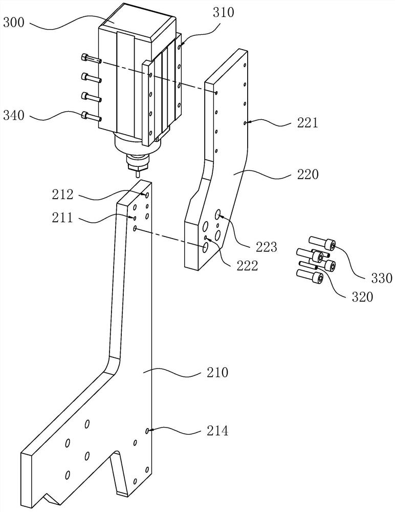
[0044] refer to figure 2 and image 3 The frame 200 includes a main bracket 210 and a motor mounting bracket 220. The main bracket 210 is provided with two first positioning holes...


PUM


Abstract

The application relates to a floating type notching machine, which relates to the technical field of rail transit maintenance. It includes a frame, a drive motor, a main shaft, a floating connection mechanism and a guide mechanism. The output shaft of the driving motor is coaxially connected, and the main shaft is slidingly connected with the output shaft of the driving motor along the axial direction of the main shaft through a floating connection mechanism. The guiding mechanism is arranged on the frame, and the main shaft is connected with the guiding mechanism. A milling cutter is coaxially arranged at one end of the . In the present application, the main shaft can slide relative to the output shaft of the drive motor along its own axis under the guiding action of the mica groove, which reduces the amount of milling of the side wall of the mica groove by the milling cutter; thus reducing the widening of the mica groove The probability of , further reduces the probability of two adjacent mica grooves being milled and connected, thereby reducing the probability of the commutator being scrapped when milling the commutator.

Description

technical field [0001] The present application relates to the field of rail transit maintenance, and in particular, to a floating groover. Background technique [0002] Most of the traction motors of trains are DC motors. The DC motor is provided with a commutator. The commutator is provided with a mica slot. The length of the mica slot is parallel to the axial direction of the main shaft of the DC motor. When the main shaft of the DC motor rotates, the commutator will rub against the brushes. After a long time of friction, the outer surface of the commutator will be worn, so the depth of the mica groove will become shallower, which will affect the performance of the DC motor. use. For this reason, after the DC motor has been used for a period of time, it is necessary to use a notching machine to mill the commutator to deepen the mica groove. [0003] refer to figure 1 , the slotting machine includes a drive motor (not shown in the figure), a main shaft 110 and a milling ...

Claims


Application Information

Patent Timeline
Patent Type & Authority Patents(China)
IPC IPC(8): B23C3/28
CPCB23C3/28
Inventor 苏本龙曹成秦稳平
Owner JINAN TAICHAN TECH CO LTD
Why Eureka
Try Eureka