Stamping car door zero-surface-difference B column section and top section structure

A section and door technology, which is applied to the top section structure and the zero-surface difference B-pillar section of the stamped car door, can solve the problems of increasing the drag coefficient of the whole vehicle, complicated manufacturing process, and unsightly appearance, and achieves a reduction in the difficulty factor of process realization, Low sliding resistance and light weight effect of glass

Pending Publication Date: 2022-01-18
SHANGHAI RONGNAN TECH CO LTD +3
View PDF0 Cites 0 Cited by
  • Summary
  • Abstract
  • Description
  • Claims
  • Application Information

AI Technical Summary

Problems solved by technology

[0002] The top section of the traditional car door glass run channel is installed on the inner panel of the door. The rubber leakage surface of the section body is more, and the Y-direction distance between the top section and the glass is generally greater than 5mm, and the Y-direction gap between the glass and the decorative panel at the B-pillar is also If it is greater than 5mm, the Y-direction gap between the top and the B-pillar is 5mm to form a step difference. This step difference will increase the drag coefficient of the vehicle and the appearance is not beautiful enough. From the perspective of the drag coefficient of the vehicle and the appearance, it is urgent to develop a zero surface Poor door sealing system structure. At present, the models with zero surface difference on the glass side in the market are generally high-end luxury cars with frameless doors. Frameless door seals are expensive, costly, and complicated to manufacture. Based on the above requirements, Development of a low-cost, simple-process new car door zero-surface-difference top section, B-pillar section structure and sealing strip

Method used


Image

  • Stamping car door zero-surface-difference B column section and top section structure
  • Stamping car door zero-surface-difference B column section and top section structure
  • Stamping car door zero-surface-difference B column section and top section structure

Examples


Embodiment Construction

[0020] In order to make the present invention more comprehensible, preferred embodiments are described in detail below with accompanying drawings.

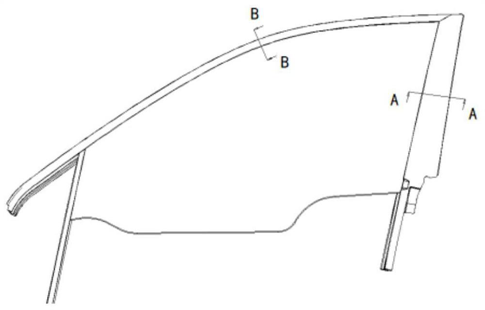
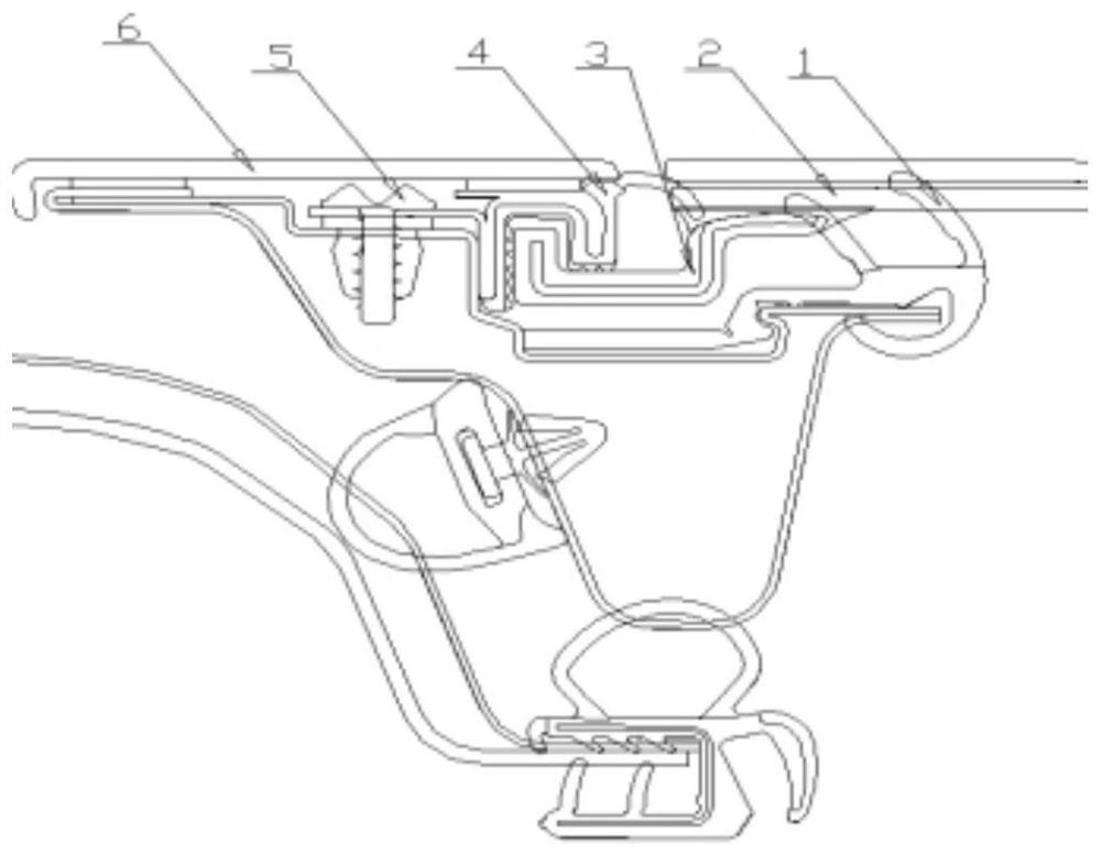
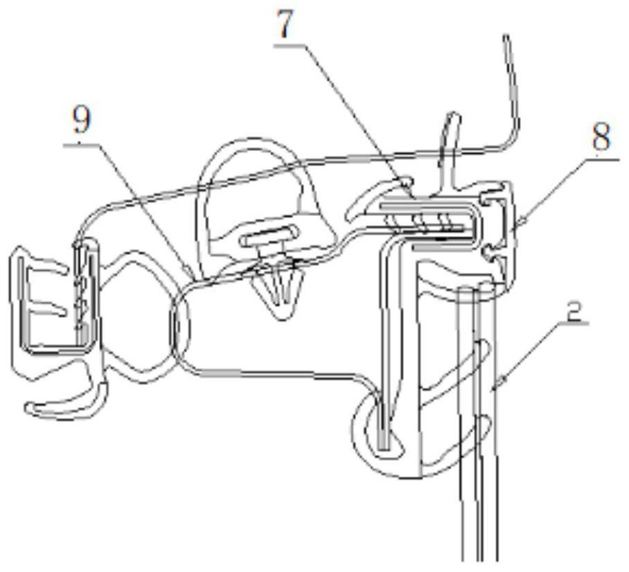
[0021] Please refer to Figure 1 to Figure 3 , a new type of stamped car door zero-surface difference B-pillar seal section and top seal strip section structure of the present invention, which is used to seal the lift glass of the car door, figure 2 On the structure of the sealing strip, there is a slider 3 parallel to the direction of the door lifting glass. The slider 3 is embedded in the sliding rail sealing strip 4. One side of the slider is connected to the glass 2 and drives the lifting glass. On the sliding rail sealing strip 4 and the sealing strip 1 of the glass run groove, the appearance surface of the glass 2 and the B-pillar trim is flush to form zero surface difference, the surface difference of the Y direction of the top section of the glass 2 is less than 3mm, the X and Y directions of the slider and the sealing st...


PUM


Abstract

The invention relates to a stamping car door zero-surface-difference B column section and top section structure which is used for sealing car door lifting glass and comprises a B column sealing strip structure and a top section sealing strip structure, the B column sealing strip structure is provided with a plastic sliding block parallel to the direction of the car door lifting glass, the sliding block is embedded in a sliding rail sealing strip, the sliding block drives the lifting glass to slide up and down in the sliding rail sealing strip and is matched with the glass guide groove sealing strip to form sealing, and the X / Y direction of the sliding block is matched with the sliding rail sealing strip and the glass guide groove to limit the X / Y direction displacement of the glass; a top section in the top section sealing strip structure is installed on an inner plate of a vehicle door, a hollow bubble-shaped structure is arranged at the contact position of the top section and glass and used for achieving the buffering and noise reduction effects when the glass is lifted to the top, the top sealing strip section is connected to the inner plate of the vehicle door in a clamped mode, and a mushroom head clamping bright strip is arranged on the top sealing strip section. The bright strip covers the appearance surface of the top section, so that the attractive effect of reducing rubber leakage is achieved.

Description

technical field [0001] The invention relates to a B-pillar cross-section and a top cross-section structure of a stamped car door of an automobile, in particular to a stamped car door with a zero-surface-difference B-pillar cross-section and a top cross-section structure. Background technique [0002] The top section of the traditional car door glass run channel is installed on the inner panel of the door. The rubber leakage surface of the section body is more, and the Y-direction distance between the top section and the glass is generally greater than 5mm, and the Y-direction gap between the glass and the decorative panel at the B-pillar is also If it is greater than 5mm, the Y-direction gap between the top and the B-pillar is 5mm to form a step difference. This step difference will increase the drag coefficient of the vehicle and the appearance is not beautiful enough. From the perspective of the drag coefficient of the vehicle and the appearance, it is urgent to develop a z...

Claims


Application Information

Patent Timeline
Patent Type & Authority Applications(China)
IPC IPC(8): B60J10/76B60J10/50B60J10/15
CPCB60J10/76B60J10/50B60J10/15
Inventor 金涛雷卫卫
Owner SHANGHAI RONGNAN TECH CO LTD
Why Eureka
Try Eureka